Unit test I key (Set 2)
advertisement

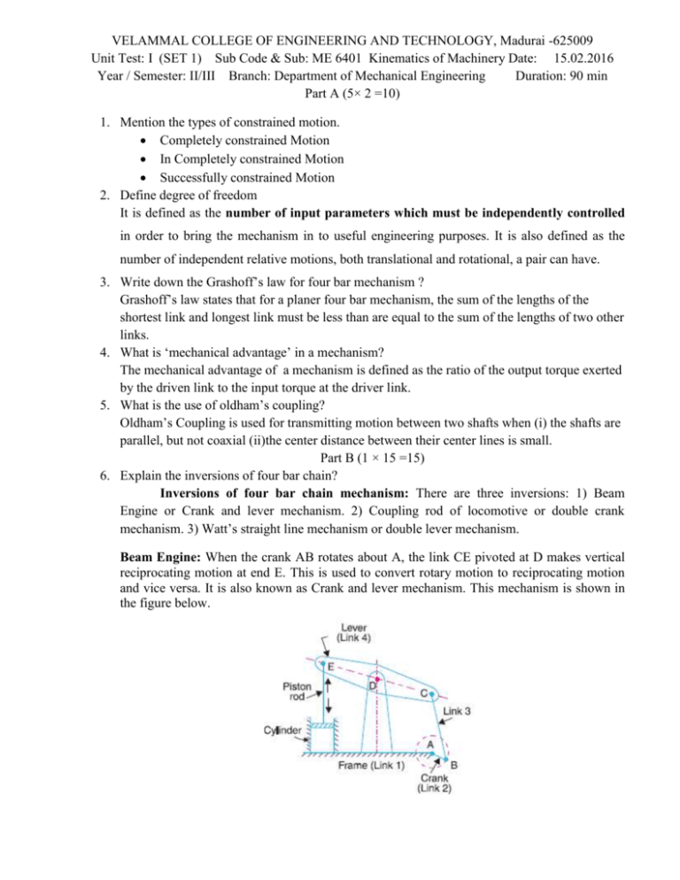
VELAMMAL COLLEGE OF ENGINEERING AND TECHNOLOGY, Madurai -625009 Unit Test: I (SET 1) Sub Code & Sub: ME 6401 Kinematics of Machinery Date: 15.02.2016 Year / Semester: II/III Branch: Department of Mechanical Engineering Duration: 90 min Part A (5× 2 =10) 1. Mention the types of constrained motion. Completely constrained Motion In Completely constrained Motion Successfully constrained Motion 2. Define degree of freedom It is defined as the number of input parameters which must be independently controlled in order to bring the mechanism in to useful engineering purposes. It is also defined as the number of independent relative motions, both translational and rotational, a pair can have. 3. Write down the Grashoff’s law for four bar mechanism ? Grashoff’s law states that for a planer four bar mechanism, the sum of the lengths of the shortest link and longest link must be less than are equal to the sum of the lengths of two other links. 4. What is ‘mechanical advantage’ in a mechanism? The mechanical advantage of a mechanism is defined as the ratio of the output torque exerted by the driven link to the input torque at the driver link. 5. What is the use of oldham’s coupling? Oldham’s Coupling is used for transmitting motion between two shafts when (i) the shafts are parallel, but not coaxial (ii)the center distance between their center lines is small. Part B (1 × 15 =15) 6. Explain the inversions of four bar chain? Inversions of four bar chain mechanism: There are three inversions: 1) Beam Engine or Crank and lever mechanism. 2) Coupling rod of locomotive or double crank mechanism. 3) Watt’s straight line mechanism or double lever mechanism. Beam Engine: When the crank AB rotates about A, the link CE pivoted at D makes vertical reciprocating motion at end E. This is used to convert rotary motion to reciprocating motion and vice versa. It is also known as Crank and lever mechanism. This mechanism is shown in the figure below. Coupling rod of locomotive: In this mechanism the length of link AD = length of link C. Also length of link AB = length of link CD. When AB rotates about A, the crank DC rotates about D. this mechanism is used for coupling locomotive wheels. Since links AB and CD work as cranks, this mechanism is also known as double crank mechanism. This is shown in the figure below. 4. 5. 6. 7. 8. 9. 10. 11. Watt’s straight line mechanism or Double lever mechanism: In this mechanism, the links AB & DE act as levers at the ends A & E of these levers are fixed. The AB & DE are parallel in the mean position of the mechanism and coupling rod BD is perpendicular to the levers AB & DE. On any small displacement of the mechanism the tracing point ‘C’ traces the shape of ‘8’, a portion of which will be approximately straight. Hence this is also an example for the approximate straight line mechanism. (OR) 7. Explain the offset slider crank mechanism and straight line mechanism with neat sketch The offset slider crank produces a (working stroke time/return stroke time) ratio greater than unity based on the rotation direction and degree of offset. With no offset and a relatively long connecting link the ratio is unity. There is an advantage with having a faster return stroke in that this motion does no useful work and takes up valuable time. Straight Line Generators : The clear obvious method of developing a straight line motion is to use a machined slideway. The obvious alternative method is to use computer controlled electric or hydraulic drive systems. However in the early days of the engineering industry these options were not available and methods of generating straight lines using linkages were developed. These systems all resulted in approximate straight lines but they were generally sufficient for the requirements. Whitworth Straight Line Mechanism Roberts Straight Line Mechanism Chebychev Straight Line Mechanism Straight line generators: Peaucellier Peaucellier linkage can convert an input circular motion to the exact straight line motion. Straight line generators: Watt mechanisms Watt's linkage (also known as the parallel linkage) is a type of mechanical linkage in which the central moving point of the linkage is constrained to travel on an approximation to a straight line. Dr.V.Anbumalar Course Coordinator VELAMMAL COLLEGE OF ENGINEERING AND TECHNOLOGY, Madurai -625009 Unit Test: I (SET 2) Sub Code & Sub: ME 6401 Kinematics of Machinery Date: 15.02.2016 Year / Semester: II/III Branch: Department of Mechanical Engineering Duration: 90 min Part A (5× 2 =10) 1. What is pantograph? An instrument for copying a drawing or plan on a different scale by a system of hinged and jointed rods 2. What are the some important inversions of four chain mechanism? There are three inversions: 1) Beam Engine or Crank and lever mechanism. 2) Coupling rod of locomotive or double crank mechanism. 3) Watt’s straight line mechanism or double lever mechanism 3. What are the applications of single slider crank mechanism? Reciprocating engine, Rotary engine, Oscillating cylinder engine Hand Pump, Scotch Yoke, Oldham's coupling, Elliptical Trammel 4. Define transmission angle? For a Four bar linkage, the transmission angle ( μ ) is defined as the acute angle between the coupler (AB) and the follower ).O4B), as indicated in Figure 5. What is link? Mention the different types of links A kinematic link, also known as an element, is defined as a single part (or an assembly of rigidly connected parts) of a machine which has motion relative to some other part of the machine. The different types of links are Rigid link, Flexible link and fluid link. Part B (1 × 15 =15) 6. Explain the inversions of Single Slider Crank Mechanism? Inversions of Slider crank Chain: It is a four bar chain having one sliding pair and three turning pairs. It is shown in the figure below the purpose of this mechanism is to convert rotary motion to reciprocating motion and vice versa. There are four inversions in a single slider chain mechanism. They are: 1) Reciprocating engine mechanism (1st inversion) 2) Oscillating cylinder engine mechanism (2nd inversion) 3) Crank and slotted lever mechanism (2nd inversion) 4) Whitworth quick return motion mechanism (3rd inversion) 5) Rotary engine mechanism (3rd inversion) 6) Bull engine mechanism (4th inversion) 7) Hand Pump (4th inversion) Reciprocating engine mechanism: In the first inversion, the link 1 i.e., the cylinder and the frame is kept fixed. The fig below shows a reciprocating engine. A slotted link 1 is fixed. When the crank 2 rotates about O, the sliding piston 4 reciprocates in the slotted link 1. This mechanism is used in steam engine, pumps, compressors, I.C. engines, etc. Whitworth quick return motion mechanism: Third inversion is obtained by fixing the crank i.e. link 2. Whitworth quick return mechanism is an application of third inversion. This mechanism is shown in the figure below. The crank OC is fixed and OQ rotates about O. The slider slides in the slotted link and generates a circle of radius CP. Link 5 connects the extension OQ provided on the opposite side of the link 1 to the ram (link 6). The rotary motion of P is taken to the ram R which reciprocates. The quick return motion mechanism is used in shapers and slotting machines. The angle covered during cutting stroke from P1 to P2 in counter clockwise direction is α or 360 -2θ. During the return stroke, the angle covered is 2θ or β. Rotary engine mechanism or Gnome Engine: Rotary engine mechanism or gnome engine is another application of third inversion. It is a rotary cylinder V – type internal combustion engine used as an aero – engine. But now Gnome engine has been replaced by Gas turbines. The Gnome engine has generally seven cylinders in one plane. The crank OA is fixed and all the connecting rods from the pistons are connected to A. In this mechanism when the pistons reciprocate in the cylinders, the whole assembly of cylinders, pistons and connecting rods rotate about the axis O, where the entire mechanical power developed, is obtained in the form of rotation of the crank shaft (OR) 7. With the help of a neat sketch explain the working of Oldham’s coupling Oldham’s coupling: The third inversion of obtained by fixing the link connecting the 2 blocks P & Q. If one block is turning through an angle, the frame and the other block will also turn through the same angle. It is shown in the figure below. An application of the third inversion of the double slider crank mechanism is Oldham’s coupling shown in the figure. This coupling is used for connecting two parallel shafts when the distance between the shafts is small. The two shafts to be connected have flanges at their ends, secured by forging. Slots are cut in the flanges. These flanges form 1 and 3. An intermediate disc having tongues at right angles and opposite sides is fitted in between the flanges. The intermediate piece forms the link 4 which slides or reciprocates in flanges 1 & 3. The link two is fixed as shown. When flange 1 turns, the intermediate disc 4 must turn through the same angle and whatever angle 4 turns, the flange 3 must turn through the same angle. Hence 1, 4 & 3 must have the same angular velocity at every instant. If the distance between the axis of the shaft is x, it will be the diameter if the circle traced by the centre of the intermediate piece. The maximum sliding speed of each tongue along its slot is given by v=xω where, ω = angular velocity of each shaft in rad/sec v = linear velocity in m/sec Dr.V.Anbumalar Course Coordinator


