930E Slide Presentation
advertisement
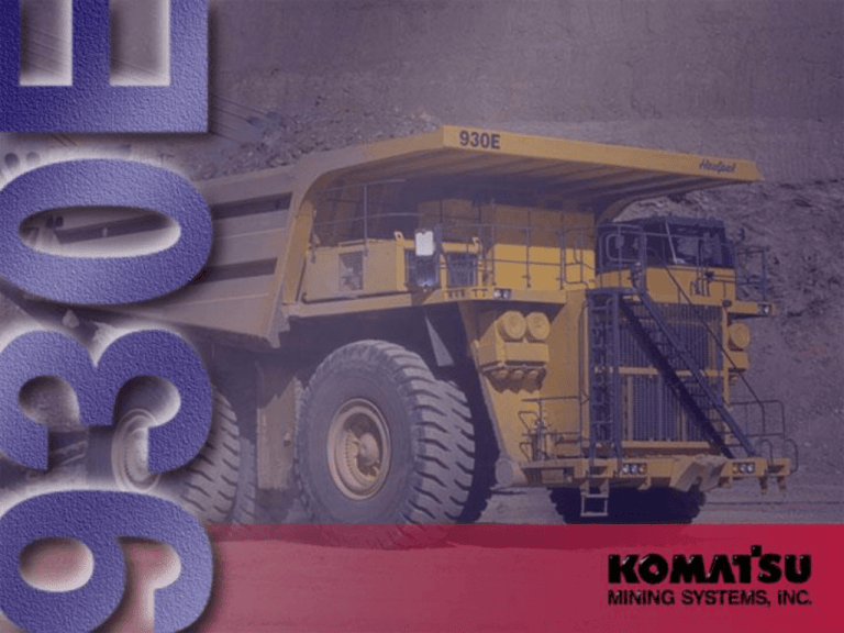
Welcome Project History • • • • • • • Large Truck Study - Late ‘80s Drive System Investigation - Mechanical - Direct Current (DC) - Alternating Current (AC) North American Locomotive Development Project Start-up - Late ‘92 Prototype - Early ‘95 Field Test - ‘96 Market Introduction - September ‘96 Development Goals • • • • Increased Productivity Decreased O&O Costs Better Performance - Speed-on-grade - Maximum Speed - Continuous Gradeability - Retarding Capability - Horsepower Utilization Across Speed Range Improved Driveability Big Is Better Philosophy OK If? • Infrastructure Can Support: - Haul Road Width - Service Bays - Maintenance Handling Equipment - Crusher Capacity - Shovel Match Big Is Better Philosophy OK If? • Cost Per Ton is Reduced - Higher Production - Fewer Trucks - Better Reliability & Availability 930E 930E Specifications • • • • • • • • • • Conventional Configuration - Rigid Frame/Single Engine/Two Axles/Six Tires Approximately 50’L X26’WX24’H 1,059,000 pound Gross Vehicle Weight 400,000+ pound Empty Vehicle Weight 320 Short Ton Payload 40 mph Maximum Speed 50/90 R 57 Tire Size Oil-cooled Service Brakes 2700 hp DDC 16V4000 Engine AC Drive System AC Electric Truck Performance • • • High speed • • Superior retarding Deep pit capacity High efficiency/ high horsepower utilization Long component life 320 Ton Componentry • MTU/DDC 16V4000 engine • G.E. drive system • - GTA-34 alternator - AC traction torque regulation GDY-85 motorized wheel Bridgestone 50/90 R57 VELS tires 930E Systems Drive System Engine Specifications Make and model Fuel Number of cylinders Operating cycle Rated brake power Flywheel power Weight (dry) MTU/DDC 16V4000 Diesel 16 4 Cycle 2700 hp (2014 kW) @ 1900 rpm 2500 hp (1865 kW) @ 1900 rpm 15,419 lb (6994 kg) 320 Ton Capacity • 20-30% more than 240 ton trucks • Up to 10% lower cost per ton Braking System • Electric retarding 5400 hp (4026 kW) • Oil-cooled, multiple disc service brakes Economics • • • Fuel savings Time cost control Maintenance cost advantage - Lowest life-cycle cost per ton Reliability Advantage • UNI-ECS electronic control • 5-10% fuel economy improvement • 12,000+ hours to overhaul Main Alternator Cutaway Control Cabinet Alternator 3-phase Voltage Measuring Module Inverter Phase Module 1 + or - Link Voltage Measuring Module Control Panel Chopper GTO Phase Module 1 and 2 Inverter Phase Modules 2 + or - Electrical Interface Cabinet Truck Control Interface Circuit Breakers/Switches Lincoln Lube System Timer Engine Drive System Diode Board Relay Boards G.E. GDY-85 Electric Wheel AC Drive System Blower Motorized Wheels Controls Pumps Alternator Retarding Grids Engine AC Control System IGBT Aux. Inverter D.I.D. Truck Control Interface (TCI) Serial Comm. Link Propulsion System Controller (PSC) Blower Cooling Air Inverters #1 #2 Rectifier Alt. Retarding Power Circuit BM1 Inverter M1 Inverter M2 BM2 Chopper Module 1 RP1 RP2 RP3 Chopper Module 2 Gradeability Comparison in Retarding 930E vs Cat 793C Grade in Percent 15 930E GVW = 1,059,000 lb 930E 793C GVW = 830,000 lb 930E 10 793C Cont. 3-min 5 Continuous mph km/h 0 0 0 5 5 10 15 20 25 30 35 40 45 10 15 20 25 30 35 40 45 50 55 60 65 70 Speed Cooling AC Drive • Induction motors no commutator, no brushes • Integral outboard planetary final drive • Proven GTA-34 traction alternator Electric Retard Advantage • High-density air cooled grids • 5400 hp (4028 kW) 3-minute retarding effort • 3300 hp (2460 kW) continuous retarding effort • 0.7 sec propel-toretard transition time KMS Quality Confirmation Attitude Past Practice - Design, Release, Produce. . . hope for the best in the field Current Practice - Design, Test, Re-design, Re-test, Produce . . . know what the field results will be KMS Joint Technology Projects 930E D575A USA H655S Japan Germany Modular Mining Vital Signs Monitoring Quality Confirmation Activity Application of K.E.S. Techniques Advanced technology, full butt-welded box sectional laddertype frame with integral ROPS supports, integral front bumper, rear tubular cross members, steel castings at all critical stress transition zones, rugged continuous horsecollar. Frame Frame Specs • • • • Rail width 12” (305 mm) Rail depth 34” (864 mm) Top and bottom plate thickness 1.77” (45 mm) Side plate thickness 0.98” (25 mm) Plate material Casting material 70,000 psi (482.3 mPa) tensile strength steel 90,000 psi (620.1 mPa) tensile strength steel Fabricated Rails 12” (305 mm) .98” (25 mm) Outside / Inside Sidesheet 34” (864 mm) Top / Bottom Bar 1.77” (45 mm) /2 0 /1 0 /9 6 /9 6 /6 /9 6 /3 /9 6 /9 6 2/ 7/ 97 4/ 18 /9 6/ 7 16 -2 0/ 97 8/ 11 /9 7 10 /1 4/ 97 15 -D ec 2/ 20 /9 8 3/ 27 /9 8 1/ 3/ 97 12 12 12 12 /2 1 200 5080 180 4572 160 4064 140 3556 120 3048 100 2540 80 2032 60 1574 40 1016 20 508 0 0 Date and Unit Length of Rejected Indications (mm) 11 Length of Rejected Indications (in) Frame Rail Ultrasonic Inspected By Model Brake System Service Brakes 2500 psi (17 229 kPa) Service Brakes Oil cooled, hydraulic-actuated, multiple disc brakes at each wheel. Traction system wheel slip/slide control. Max. service apply pressure ........ 2500 psi (17 229 kPa) Total friction area per brake ........ 15,038 in3 (97 025 cm3) Parking Brakes • • Multiple disc Spring-applied, hydraulically released Wheel Brake Locks • • • Switch-activated Rear brake only 2000 psi Electric Dynamic Retarder Brake Codes Safe and Reliable Service Brakes SAE = 331 ft Actual = 188 ft 58% Actual SAE J1473 Emergency Braking Tests Truck 101 GVW = 1,023,200 lb (464,124 kg) -- EVW = 430,800 lb (195,411 kg) Loaded on Level Loaded 8.7% Grade Empty on Level Empty 8.7% Grade Bumper to bumper 58’9” (17.9 m) 81’5” (24.8 m) Did not run Did not run Skid 43’7” (11.8 m) 65’4” (19.9 m) Did not run Did not run Radar gun 23 mph 25.5 mph (37 k\m/h) (41 km/h) All-welded steel flat floor body with horizontal bolsters and full canopy. Left and right canopy spill guards, eyebrows, rear wheel rock ejectors, body tilt cable, and rubber mounts on frame are standard. Pivot exhaust heating optional. Struck capacity Heaped capacity Loading height Body 182 yd3 (139 m3) 241 yd3 (184 m3) 21’11” (6.68 m) Canopy Sheet & Bolster Front Sheet 0.19” (5 mm) 100,000 psi (690 mPa) 0.35” (9 mm) 400 BHN Nominal Floor Sheet 0.63” (16 mm) 400 BHN Nominal Side Sheet 0.31” (8 mm) 400 BHN Nominal Bolster 0.31” (8 mm) 100,000 psi (690 mPa) tensile strength steel Heated Exhaust 930E & 830E Body Impact Plate 930E & 830E Body Impact Plate Advanced Analog Operator Environment with integral 4-post ROPS/FOPS structure (meets J1040 Apr88), adjustable Isringhausen seat w/ lumbar, passenger seat, R-12 insulation, thermopane windows, tilt steering wheel, electric windshield wipers w/ washer, tinted safety glass, Komatsu Payload Weighing System, 55,000 Btu/hr heater and defroster, 21,600 Btu/hr air conditioning (HFC-134 refrigerant). Cab Hydraulic System Hydraulic Tank Hydraulic System 350 U.S. gal (1325 L) Hydraulic Pumps Hoist & Brake Cooling Pump Tandem gear-type with output of 270 gpm (870 liters/min) at 1900 rpm and 2500 psi (17 240 kPa) Steering & Brake Pump Pressure-compensating piston with output of 60 gpm (227 liters/min) at 1900 rpm and 2750 psi (18 961 kPa) Steering Steering Cylinder Bore diameter Rod diameter Stroke Extended Retracted 6.50” 3.00” 27.29” 74.41” 47.12” Accumulator Bore Length Working Pressure 8.00” 85.75” 27.50 psi Steering Diameter Maneuverability 97’4” (24.72 m) Turning Circle 930E SAE Steering Course 25 m 5 x max width over tires B Corridor 3 Finish 2 Finish 1 C C 30 m 40 m Corridor 4 Corridor 1 10 m Corridor 2 20 m A = 1.10 x the tire track circle or 14 m, whichever is larger. B = 1.75 x the tire track circle or 22 m, whichever is larger. C = 2.00 x the maximum axle spacing or 15 m, whichever is smaller. Start 1 Start 2 1.25 x max width over tires Steering meets SAE J1511 standards Suspensions Front Suspension • • • • Maximum stroke 12.92” (328 mm) Long length bearing Forged rod and housing Large cast mounts Rear Suspension • Variable rate hydro-pneumatic with rebound control • • Maximum stroke - 9.0” (229 mm) Maximum rear axle oscillation - ± 6.5° Rear Hitch Pin High Mounted Rear Axle Hitch Pin Maximum rear axle oscillation ± 6.5° Hoist Cylinders Extended 169.07” pin to pin Retracted 65.07” pin to pin Bore diameters 1st stage 14.00” 2nd stage 11.75” 3rd stage 9.50” All stages sealed Quill for deceleration at frame-standard Stroke each stage 34.88” Hoist Cylinders Rock service, tubeless, radial tires Standard tire 50/90 R57 Tires Tire Rating Bridgestone 50/90 R57 VELS Load and inflation • • 165,000 lb at 102 psi 176,000 lb at 116 psi Specifications Specifications 30’8” 9.35 m 12’8” 3.86 m 45’9” 13.94 m RAISED 21’11” 6.68 m EMPTY 23’10” 7.26 m EMPTY 4’1” 1.25 m 14’0” 4.27 m LOADED 45° 5’11” 1.80 m EMPTY 13’10” 4.21 m 3’1” 0.94 m 20’10” 6.35 m 50’0” 15.24 m 14’8” 4.47 m 4’7” 1.40 m LOADED Specifications 27’8” 8.43 m 26’0” 7.92 m 15’2” 4.62 m 7’5” 2.26 m 19’8” 5.99 m 17’2” 5.23 m 24’2 7.37 m 26’10” 8.10 m Weight Distribution Empty Vehicle Front axle Rear axle Total (wet, 50% fuel) Loaded Vehicle Front axle Rear axle Total lb 204,289 215,181 419,470 kg 92 664 97 604 190 268 % 48.7 51.3 lb 353,000 706,000 1,059,000 kg 160 120 320 239 480 359 % 33.3 66.7 Service Capacities Cooling system Crankcase * Hydraulic system Motor gear box (each) Fuel * Includes lube oil 205 U.S. gal (776 L) 58 U.S. gal (220 L) 350 U.S. gal (1325 L) 25 U.S. gal (95 L) 1200 U.S. gal (4542 L) 930E World Population Total 100 10 67 12 11 KMS 930E AC Drive Truck “In The Dirt” Customer A. T. Massey Arco Asarco Mission Asarco Ray Barrick Chuquicamata Fording River Freeport PD Chino PD Morenci Peabody Peoria Pipeline Syncrude 100 Units Hours Location 10,193 W. Virginia 3,050 Wyoming 22,650 Arizona 8,389 Arizona 9,950 Nevada 11,163 Chile 13,522 Canada 18,790 Indonesia 99,580 New Mexico 235,883 Arizona 9,600 Wyoming 4,000 Peoria Proving Grounds 7,318 Nevada 30,050 Canada 484,138 Hours Meeting the future global mining system needs of the 21st. Century. Thank You For Visiting KMS Peoria Fuel Savings • UNI-ECS electronics engine control • Separate circuit charge air cooling • Fluid coupling fan drive Fuel Savings • Matched engine drive system • Engine speed managed by AC traction control • Drive matched to “sweet spots” on fuel map • Engine at idle speed in retarding Control Cabinet AC Traction Torque Regulator • • Torque regulator • Built in diagnostics/ diagnostics display panel • Fault and statistical data recording Wheel slip/slide control in propel and retard Rims • • • Standard five (5) piece rim 32” x 57” x 6.5” (813 mm x 1448 mm x 165 mm) Patented Phase II New Generation Rim assembly with forged center bolt flange and 62” (1575 mm) center line dual spacing Rated at 120 psi (827 kPa) cold inflation pressure
