Interface x-ray scattering, T. Trainor
advertisement
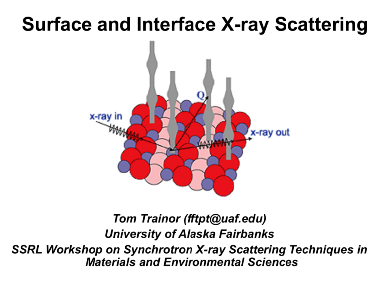
Surface and Interface X-ray Scattering Tom Trainor (fftpt@uaf.edu) University of Alaska Fairbanks SSRL Workshop on Synchrotron X-ray Scattering Techniques in Materials and Environmental Sciences Surface and Interface Scattering: Why bother? • Interface electron density profiles (Å-scale resolution) • Surface and interface roughness / correlation lengths • Interface structure/surface crystallography (1-D & 3-D) • Dependence on chemical/physical conditions • Growth/dissolution mechanisms and kinetics • Structure/binding modes of adsorbates • Structure reactivity relationships Advantages of x-rays scattering for surface and interface work • Large penetration depth experiments can be done in-situ • Liquid water, controlled atmospheres, growth chamber, etc… • Study buried interfaces • Kinematic scattering relatively straightforward analysis Disadvantages • Weak signals in general need synchrotron x-rays • Requires order Outline • A brief example • Crystal Truncation Rod – what is it ?? • Influence of surface structure • Measurements • More examples Example: Fe2O3 (0001) Surface Terminations and rxn with H2O O3-Fe-Fe-R Non-Stoichiometric, Lewis base Fe-Fe-O3-R Non-Stoichiometric, Lewis acid Fe-O3-Fe-R Stoichiometric, Lewis acid Example: Hematite (0001) Surface Terminations and rxn with H2O Surface scattering (CTR) data and best fit model(s) So what? - Structural characterization of the predominant chemical moieties present at the solid-solution interface controls on interface reactivity. What’s a crystal truncation rod? The short version… Scattering intensity that arises between bulk Bragg peaks due to the presence of a sharp termination of the crystal lattice (i.e. a surface). The direction of the scattering intensity is perpendicular to the surface and sensitive to interface structure. (20-2) (200) n̂ Real space (001) surface c a (202) 104 103 Q/2p I1/2 c* 102 101 -4 Recip. space -2 0 L 2 a* (202) L (201) (200) (20-1) 4 (20-2) What’s a crystal truncation rod? The long explanation… Lets go back to some x-ray scattering basics and recall: the scattered intensity is proportional to the square modulus of the Fourier transform of the electron density Q r kr I det R ki (r ) E2o re2 2 E E FT r R2 * FT (r ) (r ) ei Qr dV Master Equation for X-ray Scattering I E(R) 2 f 2 a, n e i Qrn n • sum over all n atoms at rn • fa,n are atomic scattering factors FT (r ) f a, n ei Qrn n f a,n n (r ) e i Qr dV Express Q in terms of reciprocal lattice coordinates Reciprocal Space Real Space Q/2p X-ray Source (plane wave) Q (-1,1) kr ki (-1,0) (0,1) (1,1) b* (1,0) a* 2 (-1,-1) (1,-1) (0,-1) sample • Q as a vector in real space Q k r - ki |Q| 4p sin( 2 / 2) • Q as a vector in reciprocal space Q 2p G 2p H a* K b* L c* Q 2p G 2p d HKL Real Space Planes Reciprocal Space Points G(1,2) (-1,1) (0,1) (1,1) b* (-1,0) (1,0) a* (-1,-1) (0,-1) (1,-1) d(H=0,K=1) b a G H a* K b* L c* | GHKL | 1/d HKL , ( HKL) d(H=1,K=1) d(H=1,K=0) (HKL) defines a plane with intercepts: bc abc ca b* abc ab c* abc a* a b c , , H K L a a* 1 a b * a c* 0 etc... Substitute for rn (real space coordinates) and Q (reciprocal space coordinates) rn R c (n 1n 2 n 3 ) rj (xyz) • Rc is the origin of the (n1n2n3) unit cell w/r/to some arbitrary “center”: Q kr ki n3 R c (n1n 2 n 3 ) n1 a n 2 b n 3 c n2 • rj is the position of the j’th atom in the unit cell, expressed in terms of its fractional coordinates (xyz): rj x a y b z c • Dot products in sum become simple to evaluate R Q 2p H a* K b* L c* Q rn Q R c Q rj Q rj 2p ( x H y K z L) Q R c 2p (n1 H n 2 K n 3 L) Substitute for Q and rn master equation: E( R) FT [ (r )] i Qrn f e a,n kr n3 Sum over n1 N1 total cells E e R ki n (N1 1)/2 Q Sum over n2 N2 total cells i 2p n1H (N1 1)/2 Sum over n3 N3 total cells n2 (N 3 1)/2 (N 2 1)/2 m i 2p n 3 L i 2p n 2 K e (N 2 1)/2 e (N 3 1)/2 fa, je i Qrj - M j e j1 Thermal disorder parameter Sum over the m atoms in the unit cell Simplify to: E Fc S1 ( H ) S2 ( K ) S3 ( L) Slit Function Structure factor of the unit cell m Fc fa, je j1 i Qrj - M j e S1 (N1 1)/2 e i 2p n1H (N1 1)/2 sin( N1πH ) sin( πH ) N1 as H integer Scattering intensity at a Bragg point: (HKL) are integers Q/2p X-ray Source (plane wave) Q (-1,1) kr ki (-1,0) (0,1) (1,1) b* (1,0) a* 2 (-1,-1) (0,-1) sample I | E | Fc 2 2 sin 2 ( N1πH ) sin 2 ( N 2 πK ) sin 2 ( N3 πL) 2 2 2 2 F N N N c 1 2 3 sin 2 (πH ) sin 2 ( πK ) sin 2 (πL) For (HKL) integer (1,-1) What about the scattering away from Bragg peak (slit functions) S3 ( L ) (N 3 1)/2 i 2p n 3 L e (N 3 1)/2 sin( N 3πL) N 3 as L integer sin( πL) 100 10 N=10 S 5 S3 2 3 80 N=10 60 40 0 20 0 -5 0 0.5 1 1.5 2 2.5 L -10 0 0.5 1 1.5 2 L • Intensity is nominal for noninteger values. • But its not zero if the xtal is finite size! 2.5 10000 S 8000 2 3 6000 N=100 4000 2000 0 0.5 1 L 1.5 2 2.5 Intensity variation between Bragg peaks as a function of xtal dimension (H=integer, K=integer). S 32 8 10 6 10 Q 4 10 kr N3=1 2 10 0 10 -2 10 -4 10 0 0.5 1 L 1.5 2 ki Intensity variation between Bragg peaks as a function of xtal dimension (H=integer, K=integer). S 32 8 10 6 10 Q 4 10 kr N3=1 N3=6 2 10 0 10 -2 10 -4 10 0 0.5 1 L 1.5 2 ki Intensity variation between Bragg peaks as a function of xtal dimension (H=integer, K=integer). S Q 2 3 kr 8 10 6 10 4 10 N3=30 2 10 N3=1 N3=6 0 10 -2 10 -4 10 0 0.5 1 L 1.5 2 ki Intensity variation between Bragg peaks as a function of xtal dimension (H=integer, K=integer). S 32 For N=1 no oscillations, scattering from a single layer. 8 10 Oscillations for N>1 due to interference between xrays scattering from the top and bottom 1 sin 2 pL 6 10 4 10 N3=30 2 N3=1 N3=6 10 0 10 Intensity variation follows the 1/sin2 profile -2 10 -4 10 0 0.5 1 1.5 L 2 At mid-point (anti-Bragg) the intensity is the same as from a single layer! The sharp boundaries of a finite size (i.e. small) crystal results in intensity between Bragg peaks However, for a large single crystal in the Bragg geometry a better model for a surface is a semi-infinite stacking of slabs 5mm 200mm n3 n2 n1 The crystal in this geometry appears infinite in-plane, and semi-infinite along the n3 direction Return to the sums and take large N1 and N2 and sum n3 from 0 (the surface) to - E Fc (N1 1)/2 e (N 2 1)/2 0 i 2p n1H i 2p n 2 K (N1 1)/2 e (001) surface termination i 2p n 3 L e (N 2 1)/2 c surface normal n1 0 Fctr ei 2p n3L 2 1 (1 e-i 2 p L ) 1 -1 0 -2 0 b a -1 -2 -3 -4 -5 I N N 2 1 2 2 Fc ( HKL) FCTR ( L) 1 Fctr 4 sin 2 (pL) 2 2 2 -2 -1 0 1 n2 2 3 n3 This is the origin of the crystal truncation rod: • For integer H and K intensity is proportional to N1xN2xFctr(L) • For non-integer H and K, S1 and S2 ~0, i.e. no sharp boundary in-plane • Therefore, rods only occur in the direction perpendicular to the surface (n3 direction) (001) surface 10 10 10 n̂ 8 Real space 6 4 1/sin2(pl) 1/4sin2(pl) 10 10 10 2 0 Q/2p -2 0 0.5 1 1.5 2 L Fctr lower at anti-Bragg than finite xtal. Why? Finite xtal has scattering from two sides, CTR is only from one side. Recip. space c* a* (202) L (201) (200) (20-1) (20-2) The scattering between Bragg peaks along a CTR results from a sharp termination of the crystal, and has a well defined functional form. But what does that tell us about the interface structure? I N N 2 1 2 2 2 Fc ( HKL) FCTR ( L) 2 Fc contains all the structure information (e.g. atomic coordinates). But so far we’ve assumed all cells are structurally equivalent. What if we add a surface cell with a different structure factor? n3 1 surface cells 0 Ebulk N1 N2 Fc, bulk( HKL) FCTR ( L) -1 -2 -3 -4 E T E b ulk E surf bulk cells Esurf N1 N2 Fc, surf ( HKL) ei2p L Therefore final expression: I N N Fbulk,cFCTR ( L) Fsurf,c 2 1 n Fc f je 2 2 i Qrj -M j e 2 Q rj (xyz) 2p ( x H y K z L) j1 • In the mid-zone between Bragg peaks FCTR ~1 • Therefore the “bulk” scattering and “surface” are of similar magnitude between Bragg peaks, ie sensitive to one bulk cell (modified by Fctr) and one surface cell 10 10 10 • The “surface” and “bulk” sum in-phase (i.e. interfere if Fsurf, different from Fbulk) 10 • Near Bragg peak the surface is completely swamped: IBragg/ ICTR > 105 10 10 8 6 4 1/4sin2(pl) 2 0 -2 0 0.5 1 1.5 L 2 Influence of surface structure: L K H Q 2 kf 10 |FHKL | ki (0 0 L) 0 10 Surface cell Bulk cell 0 0.5 1 1.5 L (r.l.u) 2 2.5 3 Known bulk structure and modifiable surface cell I N12 N 22 Fbulk,c FCT R ( L) Fsurf,c 2 Simulation of CTR profiles for a BCC bulk and surface cell for (001) surface showing sensitivity to occupancy and displacements Influence of surface structure: Bragg peak Anti-Bragg Observe several orders of magnitude intensity variation with changes in surface: • atomic site occupancy • relaxation (position) • presence of adatoms • roughness Simulations of Pb/Fe2O3 1000 (10L) A. A. Calculations as a function of surface coverage Fhkl 100 Pb occupation number 0 0.1 0.3 0.5 10 1 -10 B. Calculations as a function of the z-displacement (along the c-axis), the Pb occupation number is fixed at 0.3. -5 0 5 10 15 L(r.l.u.) 1000 (10L) B. Fhkl 100 Pb displacement 0 -0.5Å +0.5Å 10 1 -10 -5 0 L(r.l.u.) 5 10 15 Roughness “kills” rod intensity Scattering between different height features cause destructive interference Robinson b model s = 0 Å2 10 s = 1 Å2 1.0 s = 10 Å2 s = 50 Å2 0.1 -3 -2 -1 0 1 2 3 L Distinguish roughness from structure because roughness is uniform decrease in intensity Surface scattering measurement: L K H Q ki Surface cell kf Sample kf Q ki Bulk cell • Goal is to measure the intensity profile along one or more rods. • Sample orientation controls reciprocal lattice orientation. • Detector controls Q Six circle Kappa geometry diffractometer (Sector 13 APS) Surface scattering measurement: Scattered intensity is measured when the rod intersects the Ewald Sphere (from Schleputz, 2005) Multi-axis goniometer allows high degree of flexibility to access surface scattering features (from You, 1999) • Sample motions control direction of rod • Detector motions control Q General Purpose Diffractometer (APS sector 13) • Large Kappa-geometry six circle diffractometer • Leveling table with 5-degrees of freedom • High angular velocity (up to 8 deg/sec) • Small sphere of confusion (< 50 microns) • On the fly scanning • Open sample cradle, capable of supporting large sample environments weighting up to 10kg. • Liquid/solid environment cells. • Diamond Anvil Cell (DAC) • Small UHV Chamber • High temperature furnace • Open geometry also allows for mounting solid state fluorescence detectors and beam/sample viewing optics on the Psi axis bench • High load capacity detector arm supports a variety of detectors • Point detectors • CCD and Si based area detectors • Analyzer crystal for high resolution diffraction and inelastic scattering Detector Arm Entrance Flight Path Sample Environment Measurement by rocking scans: Bragg peak L Q Anti-Bragg K H ki Bragg peak kr Single crystal mineral specimen • Given a fixed Q rock the sample so the rod cuts through Ewald sphere: provide an accurate measure of the integrated intensity • Integrated intensity is corrected for geometrical factors to produce experimental structure factor (FE) for comparison with theory e.g. lsq model fitting • Symmetry equivalents are averaged to reduce the systematic errors Measurement by rocking scans: Q DL Dh Scan of rod through resolution function defined by the detector slits Int Dh Measurement by rocking scans: Q Dh DL Dh Scan of rod through resolution function defined by the detector slits Int Dh Measurement by rocking scans: Q DL Dh Scan of rod through resolution function defined by the detector slits Int Dh Measurement by rocking scans: Q Dh DL Dh Scan of rod through resolution function Int Integrated Intensity background Dh Generally not too worried about DL since rods are “slowly varying”, but can normalize data to constant value if the resolution function changes substantially Pixel array detectors with high dynamic range and fast readout means data collection speedup 10x or more CTR intersecting Ewald Sphere TDS from nearby Bragg peak CTR intersecting Ewald Sphere Powder ring Pilatus 100k Specs: 20bit, ~500x200 pixels (recently installed at APS sector 13) http://pilatus.web.psi.ch/pilatus.htm Direct Rod Scan Detector Sample Q Rod An incomplete list of practical details 1. 2. 3. What do you need: High quality (mono-lithic) crystal (mosaic kills intensity) Sample sizes from 1mm to several cm High quality surface (roughness kills intensity) Goniometer and synchrotron Know your bulk lattice parameters, coordinate system for surface and Q’s of allowed Bragg peaks Simulate before you measure Sample orientation: Find the optical surface (similar to reflectivity) Find bulk reflections (usually you know the approximate direction of the surface normal so “dummy in” a reflection). Then hunt…. Check your rod intensity and alignment Miss-cut results in tilted rods: plan your scans accordingly Check for reconstruction/surface symmetry n̂ L c* a* miss-cut surface L c* a* Reconstruction I N12 N 22 Fsurf,c 2 What’s the best way to figure out what rods to measure, what reflections to look for to align? Make a map! • What’s the symmetry of reciprocal space? • Where are the Bragg peaks on the rod? • Whats Q max? • How far to scan in L? b* • Min to max a* • What rods to measure? • (00L) gives you zinformation • (HKL) gives you x,y,z information • Simulate to test sensitivity Sample cells/environmental chambers: - Stable surface can be run in air - UHV chamber/film growth scattering chamber - Liquid / Electrochemical cells - Controlled atmosphere cells Detector Arm Entrance Flight Path Sample Environment Liquid cells (a) Transmission and (b) thin film cells (Fenter 2004) Data analysis based on least-squares structure factor routine (ROD) Semiordered overlayer Surface unit cell Bulk unit cell Ghose et al. 2007 Example: Voltage dependant water structure at a Ag(111) electrode surface Example: Structure of Mineral-Water Interfaces Example: Hydrated vs. UHV prepared a-Al2O3 (0001) surface (Eng et al., (2000) Science, 288 1029) (Guenard et al., (1997) Surf. Rev. Lett., 5 321) Example: Ordering in Thermally Oxidized Silicon A. Munkholm and S. Brennan (2004) Phys Rev. Lett. 93 036106 Some new stuff Algorithms for rapid determination of interfacial electron density profiles From Saldin et al. From Fenter et al. Baltes et. al. (1997) Phys. Rev. Lett Saldin et. al. (2001-2002) J Phys Cond Matt Fenter and Zhang (2005) Phys. Rev. B, 081401. Some new stuff Anomalous (E-dependant) surface scattering: phase constraints/chemical information From Park et al. Tweet D. J., et. al. (1992) Physical Review Letters 69(15), 2236-9. Walker F. J. and Specht E. D. (1994) In. Reson. Anomalous X-Ray Scattering, 365-87. Park C. et. al. (2005) Phys Rev. Lett., 076104 Park C. and Fenter P.A. (2006) J. Appl. Cryst. References (a very incomplete list) Reference texts: Warren B.E. (1969) X-ray Diffraction. New York: Addison-Wesley. Als-Nielsen J. and McMorrow D. (2001) Elements of Modern X-ray Physics. New York: John Wiley. Sands D.E. (1982) Vectors and Tensors in Crystallography. New York: Addison-Wesley. A few surface scattering methods papers: Robinson I. K. (1986) Phys. Rev. B 33(6), 3830-3836. ( original reference) Andrews S.R. and Cowley R.A. (1985) J. Phys C. 18, 642-6439. ( original reference) Vlieg E., et. al. (1989) Surf. Sci. 210(3), 301-321. Vlieg E. (2000) J. Appl. Crystallogr. 33(2), 401-405. ( rod analysis code) Trainor T. P., et. al.. (2002) J App Cryst 35(6), 696-701. ( rod analysis code) Fenter P. and Park C. (2004) J. App Cryst 37(6), 977-987. Fenter P. A. (2002) Reviews in Mineralogy & Geochemistry 49, 149-220. ( Excellent tech. review) Reviews Fenter P. and Sturchio N. C. (2005) Prog. Surface Science 77(5-8), 171-258. Renaud G. (1998) Surf. Sci. Rep. 32, 1-90. Robinson I.K. and Tweet D.J. (1992) Rep Prog Phys 55, 599-651. Fuoss P.H. and Brennan S. (1990) Ann Rev Mater Sci 20 365-390. Feidenhans’l R. (1989) Surf. Sci. Rep. 10, 105-188. Coordinate transformations, reciprocal space, diffractometry You H. (1999) J. App Cryst. 32 614-623. Vlieg E. (1997) J. Appl. Crystallogr. 30(5), 532-543. Toney M. (1993) Acta Cryst A49, 624-642. …. And many more…. Take advantage of periodicity of a crystal to simplify rn Atoms in a unit cell Unit cells in a crystal c c n1 -1-2 2 1 3 0 b a 2 1 r1 0 -1 r2 -2 b a -2 -1 0 1 2 3 n2 Position of the j’th atom in the cell is given by its fractional coordinates: rj x a y b z c Position of the (n1n2n3) unit cell is given by: R c (n1n 2 n 3 ) n1 a n 2 b n 3 c The position of the n’th atom in the xtal is: rn R c (n 1n 2 n 3 ) rj (xyz) n3 kr ki ki (HKL) • If Q integer HKL Bragg’s condition is satisfied Q = kr-ki kr d 2p 4p sin( 2 / 2) d HKL 2d HKL sin( ) Bragg’s Law
