Click to view the manual analysis and result table
advertisement
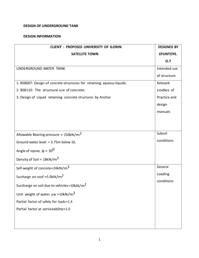
DESIGN OF UNDERGROUND TANK DESIGN INFORMATION CLIENT : PROPOSED UNIVERSITY OF ILORIN DESIGNED BY SATELLITE TOWN EFUNTOYE. O.T UNDERGROUND WATER TANK Intended use of structure 1. BS8007: Design of concrete structures for retaining aqueous liquids. Relevant 2. BS8110: The structural use of concrete. codes of 3. Design of Liquid retaining concrete structures by Anchor Practice and design manuals Allowable Bearing pressure = 250kN/m2 Subsoil Ground water level = 3.75m below GL conditions Angle of repose, φ = 300 Density of Soil = 18kN/m3 Self-weight of concrete=24kN/m3 General Surcharge on roof =5.0kN/m2 Loading conditions Surcharge on soil due to vehicles=10kN/m2 Unit weight of water, γw =10kN/m3 Partial factor of safety for loads=1.4 Partial factor at serviceability=1.0 1 Characteristic strength of steel, Grade of ribbed high-yield bars, fy Material (main bars and links) =460N/mm2 strength Characteristic strength of concrete, fcu=35N/mm2 Concrete grade = Grade 35A Severe Exposure Concrete cover, c = 40mm condition maximum allowable crack width, wmax = 0.2mm Variation temperature, T2=20oc Fall in temperature from hydration peak to ambient, T1=300c Co-efficient of linear expansion of concrete αc=12 Restraint factor, R=0.5 Population growth rate, r=2.47% 2 REFERENCE CALCULATIONS OUTPUT Assumed Average Number of people in building = 8 people Population Population of Number of Houses in the Satellite town=500 =4000 people the Total Number of people in the Satellite town satellite town = 8×500 =4000 people Population growth rate in Nigeria=2.47% C/A World fact Design year = 20years book Pn = Population at 20years (2014 est,) P0 = Initial Population n = Number of Years r = Population growth rate Punmia et Al 1995 Using the Arithmetic growth rate formula = 5976 people say Pn = P0 (1 +nr) Pn = 4000(1 + (20 × 0.0247)) = 5976 people say 6000 W.H.O Sule et Al 2010 Design population WATER DEMAND Average Per capita water demand per day = 0.05−0.1m3 Average Per Capita water demand per day of Ilorin residents 6000 people Per Capital water demand for densely = 0.046 − 0.115m3 populated area Average Water demand for densely populated area say say 0.120m3 0.120m3 water demand = Population × per capita water Demand= 6000 × 0.120 = 720m3 720m3 design volume 3 REFERENCE CALCULATION OUTPUT DIMENSIONING OF TANK Designing for a tank of 720m3 The tank is divided into two compartments. Each compartment is 360m3 The longer side is twice the shorter side for economic reason Length=7.5m Breath=7.5m Volume=L x B x H Height=6.4m Volume = (6.4 × 7.5 × 7.5)2 =720m3 LOCATING OF TANK The tank is sited or located far from sewage and septic Tanks to prevent contamination. The tank location is also of relatively high altitude the tank is also located on a soil with optimum bearing capacity STRUCTURAL DESIGN OF THE UNDERGROUND TANK SOIL PROPERTIES Soil Density = 18kN/ m3 Angle of repose = 30o Bearing capacity = kN/m2 4 Volume=720m3 REFERENCE CALCULATION OUTPUT All dimensions are in millimetres LOADING -Surcharge due to loaded vehicles on retained soil =10kN/m2 Weight of stone aggregate on roof =28.7kN/m3×0.1m = 2.87kN/m2 soil=2.87kN/m2 LAYOUT OF STRUCTURE The size of the structure is less than the length which would require and expansion joint (say 70) DESIGN ASSUMPTIONS (a)Loads Soil Pressure= Kaγ Active Earth pressure coefficient 𝐾 𝑎 = 1−sin ∅ 1+sin ∅ Soil density γ = 18kN/m3 φ = 30o Ka = 1−sin 30 1+sin 30 Surcharge on 1 = 3 = 0.33 1 Soil pressure = 18 ∗ = 6kN/m2 3 Design should be based on ground water head of 0.75m of the depth i . e 1.35m 5 REFERENCE CALCULATIONS OUTPUT Assume density of water =10kN/m3 USING BS8007 AND BS8110 (b) DESIGN FOR SEVERE EXPOSURE. Design crack width=0.2mm (c) MATERIALS Concrete grade 35A with a minimum cement content of 325Kg/m3 of finished concrete. Reinforcement steelribbed high yield bars grade 460 (d) Cover to outer layer of steel = 40mm (e) DESIGN All floor, wall and roof slab panel are designed as continuous two way spanning panels. (f) JOINTS In view of the size of the structure, no improvement joints are desirable as they are potential sources of leakage The structure will be designed as a monolithic structure. LOADING CASES (a) WELLS External soil, ground water and surcharge pressures. Soil=38.01kN/m3 Ground water =25.01kN/m3 Surcharge =3.33kN/m3 6 REFERENCE CALCULATION OUTPUT COMBINED DIAGRAM OF PRESSURE Where ground water is present the effective density of the soil is reduced due to the buoyancy effect. The effective extra load due to the presence of ground water 1 is 10 × (1 − 3)H = 6.67H (b)WET WELL FULL Pressure due to water in well Pressure due to water in well=64kN/m2 7 REFERENCE BS80072.3 CALCULATION OUTPUT No allowance will be made for the pressure resistance of the external soil BS8110 THICKNESS OF SECTIONS For ease of construction of 6.4m high wall, the minimum thickness should be 300mm. The allowable ultimate shear strength of 35 grade concrete with an assumed 0.5% of reinforcement is Vc = BS8110 Table 3.9 100As bd 0.79 × 1 1 1 Fcu 3 ( 25 ) 100As 3 ( bd ) 400 4 (d) × × γm Is assumed to be 0.5% for a minimum thickness of 300mm effective depth, d. 1 Vc = 0.79 × 35 3 (25) 1 3 × (0.5) × 1 400 4 (300) 1.25 =0.60N/mm2 Maximum ultimate force at the foot of the walls due to maximum. EXTERNAL LOADING 1 Total Force From Soil=2 ×B×H, The Pressure 1 Water=2×B×H Diagram = Surcharge = L × B 5 1 1 X 1.4 X [[ X 38.01 X 6.4] + [ X 25.01 X 3.75] 8 2 2 + [3.33 X 6.4]] = 166.12kN/m 8 166.12kn/M REFERENCE CALCULATION THE MINIMUM EFFECTIVE DEPTH OF WALL d= OUTPUT D=276.85mm V 166.2 X 103 = = 276.85mm Vc X b 0.6 X 1000 Ø Over all thickness = d + 2 + Ødistribution + C =276.85+12.5+16+40 = 345.35mm Use wall 350mm Thickness and floor 400mm thickness TOP COVER SLAB Only one needed to be designed because both sides are similar The joints between the roof slap and the walls are assumed partially free. The roof slab is a continuous twoway spanning over its supports. 9 Walls=350mm Floor=400mm REFERENCE CALCULATION OUTPUT Ly = Lx = 7.85m 𝑙𝑦 = 1.0𝑚 𝑙𝑥 SLAB SIZING Roof slab, d Using a slab 250mm thick =200mm SLAB LOADING Weight of stone aggregates to reduce Thermal cracking 28.7kN/m3 × 0.1m = 2.87kN/m2 Self weight of roof slab= 0.25 × 24 = 6.0kN/m2 Gk =dead load Total dead load = 2.87 + 6.0 = 8.87kN/m2 =8.87kN/m2 Live load due to partial access on roof (Vehicles are Qk =Live load excluded) and light construction traffic = 5.0kN/m2 =5.0kN/m2 Design load; n= 1.4Gk + 1.6Qk = 1.4 (8.87) + 1.6 (5.0) n= 20.42kN/m2 = 20.42kN/m2 BENDING MOMENT COEFFICIENTS, Maximum span moment, Msx =BSXnl2x Msy = BSynl2x Support moment, Mx = -Bxnlx2 My = -Bynlx2 LONG SPAN: Mid-span, Msy = 0.044 X 20.42 X 7.852=55.37kNm Continous edge My = -0.058 X 20.42 X 7.852 = -68.05kNm Msy =55.37kNm My =−68.05kNm SHORT SPAN: Msx =52.85kNm Mid-span, Msx = 0.042 X 20.42 X 7.852 = 52.85kNm Mx =0kNm Continuous edges, mx = 0kN m 10 REFERENCE CALCULATION OUTPUT MAIN REINFORCEMENT Assuming the use of 16mm diameter steel in direction of short-span. ∅ d=h–c-2 = 250 − 40 − 16 2 = 202mm SHORT SPAN: Midspan moment Msx = 52.85kNm k= M 52.68 X 10^6 = 35 X 1000 X 2022 = 0.037 Fcu bd2 K=0.037 K<0.156 : no need of compression reinforcement Z=lad la = 0.5 + √0.25 − la = 0.5 + √0.25 − k 0.9 0.037 0.9 la = 0.957 z = 0.957 X 202 = 193.32 m As = 0.87 ×f y lad 52.85 X 10⁶ As = 0.87 X 460 X 0.957 X 202 Z=193.32 As = 683.13mm2 Provide Y16@250mmc/c B(804mm 2) Y16@250mm c/c This is the minimum reinforcement that satisfied the B(804mm2) strength CALCULATION OF DESIGN CRACK WIDTH Thickness of wall = 350mm Applied service moment= 350m Reinforced area = 804mm2, cover= 40 11 REFERENCE CALCULATION OUTPUT ∅ Depth (d) = h – c - 2 d = 350 – 40 – ½ x 16 = 302mm ᵨ= As required bd = 804 100 ×302 = 2.66 × 10⁻³ modular ratio = 𝜀 s, = 200KN/mm2 𝜀 c, = ½ x 27 = 13.5KN/mm2 єs αe = єc =14.8 αeᵨ = 14.8 x 0.00266 = 0.394 DEPTH OF NEUTRAL AXIS IS GIVEN BY x 𝟐 = αeᵨ (√𝟏 + αeᵨ − 𝟏) d x 𝟐 = 0.0394 (√𝟏 + 0.0394 − 𝟏) d x = 0.244 d x = 0.244 × 302 = 73.7mm Lever arm Z = d – x/3 = 302 – 73.7/3 Z= 277.4mm ms Steel tensile stress, Fs = Z As 52.85 X 10⁶ FS = 277.4 X 804 = 236.96 N/mm2 CONCRETE COMPRESSIVE STRESS, FCB 2ms Fcb = Z bx = 2x52.85 × 106 277.4 × 1000 × 73.7 Fcb = 5.19N/mm2 CHECK STRESS LEVEL Fs =236.96 < 368 0.45 Fcu = 0.45 × 35 = 15.7 Fcb=5.19<15.7 Fcb = 5.19<15.7 ok stress level OK 0.8Fy = 0.8 × 460 = 368 Fs = 236.96 < 368 Ok 12 REFERENCE CALCULATION ϵ1 = h−x d−x Fs × Es 350−73.7 = 302−73.7 × OUTPUT 236.96 200 ×103 = 1.43 × 10⁻³ 2 2 s ∅ ∅ ∝cr = √(2) + (c + 2) - 2 200 2 = √( 2 ) + (40 + 16 2 16 2 ) - 2 = 102.9mm FOR LIMITING DESIGN SURFACE CRACK b(h − x)(a − x) 3Es As (d − x) ϵ2 = ϵ2 = 1000(350 − 73.7)(350 − 73.7) 3 × 200 × 103 × 804(302 − 73.7) ϵ2 = 6.9318 × 10⁻⁴ Em = ϵ1 − ϵ2 Em = 1.43 × 10⁻³ − 6.9318 × 10⁻⁴ Em = 7.368 × 10⁻⁴ DESIGN CRACK WIDTH w= w= 3acr Em 1+2 ( acr − Emin n−x 3 × 102.9 × 7.368 × 10−4 102.9− 40 1 + 2 ( 350−73.7 ) W = 0.156mm VERTICAL REINFORCEMENT Table A2.6 ) Design Cack width=0.2m h=350mm Limiting moment 60.8kNm Service steel stress 190N/mm2 Ultimate shear capacity 167KN/m 13 Crack width = 0.156mm less than allowable 0.2mm REFERENCE CALCULATION OUTPUT Moment =52.85KNm Fs = 52.85 60.8 × 190 = 165.16N/mm2 165.16 < 190 satisfactory m As = zf s 52.85 × 10⁶ As = 190 × 193.32 As = 1438.8mm2 Provide Y16 @ 125mm c/c Y16@ 125mm c/c (As provided 1610) DEFLECTED CHECK FOR ROOF SLAB Basic span depth ratio of 2-way slab=26 Fs = 2 As required × 460 × 3 As provided mf = 0.55 + Fs = 477 − fs 120 (0.9 + m bd2 ) 2 683.13 × 460 × = 166.26 3 1260 m 52.85 × 106 = = 1.29 bd2 1000 × 2022 477 − 166.26 mf = 0.55 + = 1.73 120 (0.9 + 1.29) limiting span = basic ratio × mf effective depth =26 × 1.73 = 44.98 actual span 7850 = = 38.86 effective depth 202 Limiting span ratio 44.98 > Actual span Limiting span ratio > Actual span ratio, ratio= 38.86 Deflection deflection Ok ok 14 REFERENCE CALCULATION CALCULATION OF MINIMUM OF CONTINUOUS CONSTRUCTION = (7.5 × 2) + (0.35 × 3) = 16.05m Fall in temperature Hydration peak to ambient, T1 = 300c Variation in temperature, T2 = 200c Design crack width=0.2mm αc = coefficient of linear expansion of concrete= 12 Restraint factor R=0.5 NET EFFECTIVE CONTRACTION STRAIN = R × αc × T1 = 0.5 × 12 × 30 = 180microstrain Maximum allowable crack width = 0.2mm w 0.2 Smax = R × α c ×T = 180 ×10−6 = 1111mm Also Smax = fct fb × Ø 2ρ fct 2 = fb 3 2 Smax = 3 × Smax = ρ= Table 5.1 Anchor 16 2ρ 5.33 ρ 5.33 × 100 = 0.48% 1111 Also Pcrit = fct fy = 1.6 460 × 100 = 0.35% FOR THE ROOF SLAB Minimum area of reinforcement =0.48 × area of reinforcement =0.48% × 1000 × 250 =1200mm2 15 OUTPUT REFERENCE CALCULATION Provide Y12@75mm c/c(1510mm2) each face OUTPUT Provide Y12@ 75mmc/c for distribution FOR WALL Minimum area of reinforcement= 0.48% × Area = 0.48 100 × 1000 × 350= 1680mm2 Provide Y16@100mm c/c for both faces (2010mm2) Provide Y16 @ 100mm c/c both faces (2010mm2) FORCES ON WALLS Effective height of walls, center to center of roof slab to floor slab. = 6400 + 350 2 + 250 2 assuming a base Thickness of 350mm = 6700mm The walls panels are loaded triangularly due to water and soil pressure and rectangularly due to surcharge pressure. It is convenient to replace the surcharge pressure by the equivalent soil pressures. 16 REFERENCE CALCULATION By using the similar triangles approach 6.7 x = 40.2 43.53 0.7 × 43.53 x= = 7.255 40.2 Say 7.260 h = equivalent height = 7.26m LOADING CASE1 External soil pressure (including surcharge) =43.53kN/m2 Ground water = 6.67 × H = 6.67 × 1.5 =10.00kN/m2 Total = 53.53kN/m2 CASE 2 Internal water pressure = γH = 10 × 6.7 = 67kN/m2 WALL A height of wall = 6.7m length of wall = 7.85m ratio Lx Lz 7.85 = 6.70 = 1.17 Mv = Vertical span MH = Horizontal span +M = Tension on unloaded face -M = Tension on loaded face CASE 1 SOIL + WATER (TANK EMPTY) −Mv = 0.046 × 53.53 × 7.26 × 6.7 = 119.8 +Mv = 0.017 × 53.53 × 7.26 × 6.7 = 44.26 −MH = 0.02 × 53.53 × 7.852 = 65.97 17 OUTPUT REFERENCE CALCULATION +MH = 0.008 × 53.53 × 7.8522 = 26.39 CASE 2 INTERNAL WATER (TANK FULL) −Mv = 0.046 × 67 × 6.722 = 138.4 +Mv = 0.017 × 67 × 6.722 = 51.13 −MH = 0.02 × 67 × 7.8522 = 82.57 +MH = 0.008 × 67 × 7.8522 = 33.03 WALL B Length of wall = Lx = 7.850 Height of wall = Lz = 6.70m l Ratio = lx = z 7.850 6.70 = 1.17 CASE 1: one compartment full, the other empty As case 2 wall A, on each face Wall C just as wall A WALL D Length of wall = Lx = 7.850 Height of wall = Lz = 6.70m l Ratio = lx = z 7.850 6.70 = 1.17 CASE 1, SOIL AND WATER (TANK EMPTY) Same as case 1 wall A CASE 1 INTERNAL WATER (TANK FULL) Same as case 2 wall A walls E,F,G same as Wall A DIRECT FORCES All External loads cause compressive horizontal forces in the walls which are resisted by the concrete in compression. The value of the compressive stress is low and 18 OUTPUT REFERENCE CALCULATION may be ignored. The load due to water in both wells cause tension in the walls which is evaluated below TENSION IN WALL D Tension in wall D due to pressure on walls A and B. Maximum water pressure = 10 × 6.7 = 67kN/m2 Average water pressure over the lowest 1m height of wall = 10 × (6.7+5.7) = 62kN/m2 2 Total force = 62 × 7.85 = 486.7kN/m height Force per meter height on wall D and F = 486.7 2 =243.4kN The effect of the floor is neglected but it is conservative Assuming a service steel stress of Fs = 240N/mm2 T 243.4 × 10³ As = = = 507mm2 2fs 2 × 240 FLOOR SLAB The soil pressure under the floor slab is due to the imposed weight of the structure. TAKING A COMPART AND ANALYZING THE LOADS: (1) Roof Self weight = 24 × 0.25 × 16.05 × 8.2 = 789.66kN (2) Imposed load on roof Stone aggregate and live load = (2.87 + 5) × 18.05 × 8.2 = 1035.77kN (3)Walls DEFG = 2(16.05×0.35×6.4×24) = 1725.6kN Walls ABC = 3(7.5 × 0.35 × 6.4 × 24) = 1209.6kN (4)Floor slab = 24 × 0.40 × 16.05 × 8.2 = 1263.5kN Total Load = 5234.43kN Assuming uniform distribution over the floor area the soil pressures 19 OUTPUT REFERENCE CALCULATION FOS load Bearing pressure = Base Area = 1.5 ×5234.43 16.05 ×8.2 OUTPUT = 59.66kN/m2 Designing for the base of one compartment and providing for the other. Before designing the base, structure has to be checked for flotation Weight of Empty Tank Roof self weight = 789.66kN Walls DEFG = 1725.6kN Walls ABC = 1209.6kN Floor slab = 1263.5kN Total weight = 4988.36kN UPLIFT DUE TO GROUND WATER weight of water displaced = 10 × 16.05 × 18.2 × 1.9 = 2566.39kN Weight of empty tank 4988.36 = = 3990.7kN Factor of safety 1.25 weight of empty tank > uplift due to ground water 20 REFERENCE CALCULATION OUTPUT Floatation satisfied L For the floor slab Ly = x Floatation check 7850 7850 satisfied. =1 Floor slab is two way slab Assuming simply supported and allowing for fixing moments later +Mx = 0.055 × 65.66 × 7.852 = 222.5kNm +My = 0.056 × 65.66 × 7.852 = 226.59kNm UDL FROM WALL E 24 × 0.35 × 6.4 × 7.85 = 6.43kN 8.2 × 16.02 UDL FROM WALL C = 24 × 2 × 0.35 × 6.4 × 7.85 = 6.43kN 8.2 × 16.02 Moment from wall E = wl2 8 = 6.43 × 7.852 8 = 49.53kNm WALL B (INTERNAL) max + mx = 222.5 − 49.53 = 197.7kNm 2 max + mx = 226.5 − 49.58 = 177.7kNm 21 REFERENCE CALCULATION OUTPUT FLOOR REINFORCEMENT Floor Thickness=400mm Cover = 40mm Effective depth of inner layer= 400-40-20-10=300mm +Mx = 197.7kNm K= m fcu bd2 = 197.7 × 10⁶ 35 × 1000 × 3002 K = 0.0627 < 0.156 Z = lad la = 0.5 + √0.25 − 0.0627 0.9 Z = 0.924d Z = 277.4 197.7 × 10⁶ As = 0.87 × 460 × 277.4 As = 1780.85mm2 Provide Y20@ 150mm c/c TF (2090mm2) +My = 177KNm K= m 177 × 106 = fcu bd2 35 × 1000 × 3002 22 Floor Y20@ 150mm REFERENCE CALCULATION OUTPUT K = 0.0562 < 0.156 Z = lad la = 0.5 + √0.25 − 0.0562 0.9 Z = 0.93d Z = 279.9 177 × 106 As = 0.87 × 460 × 279.9 As = 1580.13mm2 Provide Y20@175mm TF(As Provided 1800mm2) MINIMUM REINFORCEMENT IN FLOOR Fall in temperature from hydration peak to ambient, T1 = 300c Variation in temperature, T2 = 200c Design Crack width = 0.2mm αc = Coefficient of linear expansion of concrete = 12 Restraint factor, R=0.5 Net effective contraction strain R × αc × T1 0.5 × 12 × 30 = 180 micro strain Maximum allowable crack width = 0.2mm w : Smax = crack space = R × ∝ c Ø = 20mm Also Smax = 𝑓𝑐𝑡 𝑓𝑏 × ∅ 2𝜌 𝑓𝑐𝑡 2 = 𝑓𝑏 3 23 ×T = 0.2 180 × 10−6 = 1111mm Y20@ 175mm REFERENCE CALCULATION Smax = Smax = 3 3 OUTPUT 20 × 2𝜌 20 3𝜌 Smax = 1111mm :ρ= 20 1111 ×3 Also ρcrit = = 0.60% fct fy 1.6 = 460 × 100 = 0.35% Asmin = %bh Asmin = 0.60% × 1000 × 400 Asmin = 2400mm2 Provide Y20@ 125mm c/c As provided (2510mm2) ARRANGEMENT OF REINFORCEMENT FOR FLOOR SLAB TOP FACE Provide Y20@ 150mm c/c(TF) As provided(2090mm2) Provide Y20@ 175mm c/c(TF) As provided (1800mm2) BOTTOM FACE Provide Y20@125mm c/c As provided (1800mm2) WALL REINFORCEMENTS Table A2.6 Anchor Wall Thickness = 350mm Cover=40mm Effective depth to inner layer of reinforcement =350-40-10-12=286mm The minimum reinforcement calculated earlier is Y16@100mm c/c for each face (2010mm2) For Y16@100mm c/c moment=98.1KNm 24 Y20@ 125mm EW REFERENCE CALCULATION OUTPUT WALL A HORIZONTAL REINFORCEMENT All moment are less than 98.1kNm/m Therefore for bending use Y16@100mm c/c As=2010mm2 Adding reinforcement area to cater for direct Tension =2010mm2 + 507mm2 = 2517mm2 Y20@100mm EF Provide Y20@100mm c/c EF(3140mm2) for walls VERTICAL REINFORCEMENT Maximum vertical moment=138.4kNm/m Y20@100EF for all Allowable moment = 173kNm/m walls Wall B, C, D, E, F, G are provided with the same reinforcement. 25
