Beam Elements
advertisement
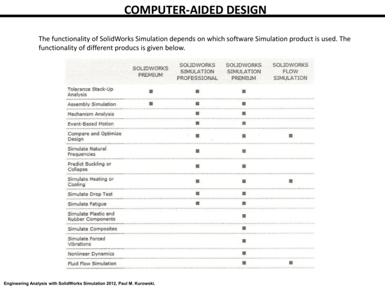
COMPUTER-AIDED DESIGN The functionality of SolidWorks Simulation depends on which software Simulation product is used. The functionality of different producs is given below. Engineering Analysis with SolidWorks Simulation 2012, Paul M. Kurowski. Fundamental Steps in an FEA Analysis The starting point for any FEA project is a model, which can be a part or an assembly. First, material properties, loads, and restraints are defined. Next, the model geometry is split into relatively small and simply shaped entities called finite elements. The elements are called “finite” to emphasize the fact that they are not infinitesmally small, but relatively small in comparison to the overall model size. Creating finite elements is commonly called meshing. When working with finite elements, the SolidWorks Simulation solver approximates the sought solution (for example stress) by assembling the solutions for individual elements. From the perspective of FEA software, each application of FEA requires three steps. Preprocessing of the FEA model, which involves defining the model and then splitting it into finite elements (meshing). Solving for desired results Post-processing for results analysis We will follow the above three steps in every exercise. From the perspective of FEA methodology, we can list the following FEA steps. Building the mathematical model Building the finite element model by discretizing the mathematical model Solving the finite element model Analyzing the results Figure 1. Steps of an FEA analysis. Engineering Analysis with SolidWorks Simulation 2012, Paul M. Kurowski. Errors in FEA: The process illustrated in Figure 1 introduces unavoidable errors. Formulation of a mathematical model introduces modeling errors (also called idealization errors), discretization of the mathematical model introduces discretization errors, and solving introduces solution errors. Of these three types of errors, only discretization errors are specific to FEA. Modeling errors affecting the mathematical model are introduced before FEA is utilized and can only be controlled using correct modeling techniques. Solution errors are caused by the accumulation of round-off errors. Meshing splits continuous mathematical models into finite elements. The type of elements created by this process depends on the type of geometry meshed. SolidWorks Simulation offers three types of three dimensional (3D) elements; solid elements for meshing solid geometry, shell elements for meshing surface geometry and beam elements for meshing wire frame geometry. SolidWorks Simulation also works with two dimensional (2D) elements; plane stress elements, plane strain elements, axi-symmetric elements. In FEA terminology, “solid” denotes the type of element used to mesh the solid CAD geometry. The type of geometry that is most often used for analysis with SolidWorks Simulation is solid CAD geometry. Meshing of this geometry is accomplished with tetrahedral solid elements, commonly called “tets” in FEA jargon. The tetrahedral solid elements in SolidWorks Simulation can either be first order elements (draft quality), or second order elements (high quality). The user decides whether to use draft quality or high quality elements for meshing. However, as we will soon prove, only high quality elements should be used for an analysis of any importance. The difference between first and second order tetrahedral elements is illustrated in Figure 2. The edges of a second order element before defomation may either be straight or curvilinear, depending on how the element has been mapped to model the actual geometry. Consequently, the faces of a second order element before deformation may be flat or curved. After deformation, edges of a second order element may either assume a different curvilinear shape or acquire a curvilinear shape if they were initially straight. 4 nodes uy In a first order element, edges are straight and faces are flat. After deformation the edges and faces must retain these properties. ux uz 3 DOFs at each node Total DOF= 12 10 nodes 3 DOFs at each node Total DOF= 30 Figure 2. Differences between first and second order tetrahedral elements. Engineering Analysis with SolidWorks Simulation 2012, Paul M. Kurowski. First order tetrahedral elements model the linear field of displacement inside their volume, on faces, and along edges. The linear (or first order) displacement field gives these elements their name: first order elements. If you recall from Mechanics of Materials, strain is the first derivarive of displacement. Since the displacement field is linear, the strain field is constant. Consequently the stress field is also constant in first order tetrahedral elements. This situation imposes a very severe limitation on the capability of a mesh constructed with first order elements to model stress distribution of any complex model. To make matters worse, straight edges and flat faces cannot map properly to curvilinear geometry, as illustrated in Figure 3. Figure 3. Mapping of a curvilinear geometry with first and second order elements. Second order tetrahedral elements have ten nodes and model the second order (parabolic) displacement field and first order (linear) stress field in their volume, on faces and along edges. The edges and faces of second order tetrahedral elements can be curvilinear before and after deformation, therefore these elements can be mapped preciseley to curved surfaces as illustrated in Figure 3. Even though these elements are more computationally demanding than first order elements, second order tetrahedral elements are used for the majority of analyses with SolidWorks Simulation because of their much better mapping and stress modeling capabilities. Shell Elements: Shell elements are created by meshing surfaces or faces of solid geometry. Shell elements are primarily used for analyzing thin-walled structures. Since surface geometry does not carry information about thickness, the user must provide this information. Similar to solid elements, shell elements also come in draft and high quality with analogous consequences with respect to their ability to map to curvilinear geometry, as shown in Figure 4. Mid side node First order Second order Figure 4. First and second order shell elements. Engineering Analysis with SolidWorks Simulation 2012, Paul M. Kurowski. Certain classes of shapes can be modeled using either solid or shell elements, such as the plate shown in Figure 5. Often the nature of geometry dictates what type of element should be used for meshing. For example, a part produced by casting would be meshed with solid elements, while a sheet metal structure would be best meshed with shell elements. Figure 5. Plate modeled with solid elements and shell elements. The actual choice between solids and shells depends on the particular requirements of analysis and sometimes on personal preferences. Beam Elements: Beam elements are created by meshing curves (wireframe geometry). They are a natural choice for meshing weldments. A beam element does not have any physical dimensions in the directions normal to its length. It is possible to think of a beam element as a line with assigned cross section properties (Figure 6). Figure 6. Conceptual representation of a beam element. A beam element is a line with assigned properties of a beam cross section as required by beam theory. This illustration conceptualizes how a curve (here a straight line) defines an I-beam but does not represent actual geometry of the beam cross section. Engineering Analysis with SolidWorks Simulation 2012, Paul M. Kurowski. Nodal Degrees of Freedom: The degrees of freedom (DOF) af a node in a finite element mesh define the ability of the node to perform translation and rotation. The number of degrees of freedom that a node possesses depends on the element type. In SolidWorks Simulation, nodes of solid elements have three degrees of freedom, while nodes of shell elements have six degrees of freedom. This is because in order to describe transformation of a solid element from the original to the deformed shape, we only need to know three translational components of nodal displacement. In the case of shell and beam elements, we need to know the translational components of nodal displacements and the rotational displacement components. Using solid elements we study how a 3D structure deforms under a load. Using shell elements we study how a 3D structure with one dimension “collapsed” deforms under a load. This collapsed dimension is thickness which is not represented explicitly in the model geometry. Beam elements are intended to study 3D structures with two dimensions removed from the geometry and not represented explicitly by model geometry. It is important to point out that solids, shells and beams are all 3D elements capable of deformation in 3D space. 2D Elements: There are also cases where a structure’s response to load can be fully described by 2D elements that have only two in-plane degrees of freedom. The are plane stress, plane strain and axi-symmetric elements. Plane stress elements are intended for the analysis of thin planar structures loaded in- plane, where out-ofplane stress is assumed to be equal zero. Plane strain elements are intended for the analysis of thick prismatic structures loaded in-plane, where out-of-plane strain is assumed to be equal zero. Axi-symmetric elements are intended for the analysis of axi-symmetric structures under axisymmetric load. Figure 7. 2D elements. Figure 8. Basic element library of SolidWorks Simulation.
