pin hole center to center measurements
advertisement
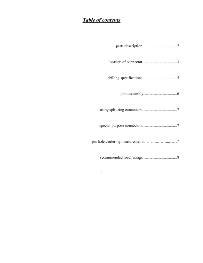
Table of contents parts description...................................2 location of connector...................................3 drilling specifications...................................5 joint assembly..................................6 using split-ring connectors...................................7 special purpose connectors...................................7 pin hole centering measurements………..……...……7 recommended load ratings...................................8 . PARTS DESCRIPTION A : connecting tube The connecting tube is inserted equally into both joint members, perpendicularly to the contact area of the joint. B : expanding pin The expanding pins are inserted through each joint member, perpendicularly to the connecting tube, which they cross through slots "C". C : pin slot The elongated pin slots receive the expanding pins and provide room for expansion. D : tightening bolt Each expanding pin has a through bolt that can drive a pair of wedges "E" towards each other. E : expansion wedges The expansion wedges, when forced towards each other, pry apart both halves of the pin, expanding it in one direction. F : positioning shoulder These protrusions on the sides of the pins stop them at the correct location 2 CONNECTOR LOCATION Regardless of other considerations, access to each pin's expanding mechanism must be retained throughout structure assembly. Access must also be retained after completion if unseasoned lumber was used. Permanent accessibility is always a desirable feature. 1 - Right angle connections. - single connector: the connector should be located at the geometrical center of the contact area (fig.1). - double connector: the connectors should be located along the greater median line of the contact area, spaced equally from its midpoint, not less than 6.5 cm (2-1/2") apart (fig.2) - The member perpendicular to the connector tube may have the tube hole drilled right through, to allow insertion of the tube after the members have been positioned. This is often necessary when assembling configurations containing angled joints, such as trusses. fig. 1 fig. 2 3 2 - Angled connections. The connector should be located along the greater median line of the contact area, at a point that optimizes its effectiveness without compromising the members’ integrity. This ensures sufficient end distance from the pin, without being closer to the heel of the sloping member than necessary. Note: The connector tube cannot be allowed to protrude nor to be truncated in any way. In most cases, using the formula described in fig.3 will be satisfactory for a single connector, and also for a double if the connectors are kept a minimum of 6.5 cm (2-1/2") apart (fig.4). Either half of the tube hole may be drilled right through, to allow insertion of the tube after the members have been positioned. This is often necessary when assembling configurations containing angled joints, such as trusses. fig. 3 fig. 4 4 DRILLING Holes required for connector installation must be clean, straight, accurate bores best obtained with a drill press, when possible, or with a special drilling guide. Auger, sawtooth or twist drill bits are suitable, ordinary spade bits are not. A single size (1-1/8” or 28mm)* is required for all holes. This includes the holes for pins, as room is needed for 8mm (5/16") expansion. Bits must be able to drill into the wood to a depth of 12.5 cm (5"), cross- grain or end-grain. While some inaccuracy is acceptable for the pin bores, to the extent that pin insertion and expansion are still possible, both holes for the connector tube must be exactly perpendicular to the joint's contact area in order to line up Having to enlarge these would result in possible lateral movement of the joint, at the detriment of its resistance to sheer. Location of drilled holes, illustrated below (fig. 5), should be: - midway through the thickness of the members, for the tube, - centered exactly 10cm (3-15/16") away from the contact area for the pins. Pin bores must be perpendicular to the tube bore and centered on it. * (We recommend 1-1/8” or 28mm drill bits for all holes. 1-1/16” may be used for the pipe hole in seasoned lumber.) fig. 5 5 JOINT ASSEMBLY Careful consideration should be given to the assembly sequence of the structure being built. First of all, the 24cm (9-1/2") tube has to be inserted into one member of the joint, and then the other member has to slip over the protruding half. At some point the two parts of each joint have to be 12cm (4-3/4") apart prior to being connected. In situations where this is not possible (trusses for example), one of the members may have its tube hole drilled right through, to allow insertion of the tube after the members have been positioned. While this doesn't affect the strength of the joint, it requires more drilling, as well as plugging the extra perforation where it might not be concealed. Good planning sould keep this to a minimum. Assembling the joint is otherwise quite simple: - insert the tube into either one of the members - rotate it until the pin slot is in line with the pin bore - insert a positioning tool to hold it in place - slip the other member over the protruding part of the tube - insert the second positioning tool right through the 2nd member's pin hole and lever the tube away from the opposite end, until all play has been picked up. There should now be enough room to insert both pins. (Use the special insertion tool.) - using the Allen wrench, screw in the tightening bolt(s). If there is no more than 3mm (1/8") of play to be picked up before the joint starts to tighten, only 1 pin needs to be expanded. Otherwise try to divide the action of both pins equally. In all cases, do not underestimate the tremendous power of the expanding pins: overtightening will indent the wood the pins are resting on and reduce the availability of further expansion which might be needed if the lumber shrinks. Generally, 1/2 to 3/4 of a turn past the point where the joint is firm is quite sufficient - testing a joint with 2 scraps is a good way to feel what's right if you are new to the connector. NB Positioning Tools (pair) and Insertion Tool are available from supplier 6 SPLIT RING CONNECTORS To achieve greater shear resistance than the recommended rating (see "recommended load ratings" p8), for example with joist-bearing beams, standard split ring connectors (also called timber rings) can easily be added to the connection. Using the proper grooving tool, make grooves on both faces of the joint, centered on the connecting tube, before drilling for the tube. For specific ratings, consult with us or with an engineer. SPECIAL PURPOSE CONNECTORS The connector lends itself to an almost infinite variety of modifications for unusual situations. While some will become off-the-shelf items, others can be obtained as special orders. Here are some examples: • connectors to anchor timbers to foundations or masonry walls • connectors to fasten timbers to existing structures • elongated connectors to fasten 2 beams through a post • angled clusters for conical roof apexes • roof sill to rafter connectors, including polygonal structure’s hip to sill corner tie-up PIN HOLE CENTER TO CENTER MEASUREMENTS for various size TIMBERLINX (1-1/8” or 28mm bit only) A 095 B 095 A 135 A 155 9-1/2” connector 9-1/2” connector 13-1/2” connector 15-1/2” connector 7-3/4” 7-3/4” 11-3/4” 13-3/4” B 155 A 175 B 175 A 475 AA675 AA675 15-1/2” connector 13-3/4” 17-1/2” connector 15-3/4” 17-1/2” connector 15-3/4” 4-3/4” half connector 3-7/8” plus threaded rod 6-3/4” half connector Double Slots 2-7/8” 5-7/8” plus threaded rod 6-3/4” half connector Double Slots 3-7/8” 5-7/8” plus threaded rod 7 8 RECOMMENDED LOAD RATINGS Standard term loading² Short term loading² Property single connector (kN) (lb) two connectors³ (kN) (lb) single connector (kN) (lb) two connectors³ (kN) (lb) Tension parallel to grain 12.0 2690 17.4 3920 13.7 3090 20.0 4510 Tension perpend. to grain 11.2 2510 17.4 3920 12.9 2890 20.0 4510 Shear parallel to 16.4 3700 - - 18.9 4260 - - 7.3 1640 - - 8.4 1890 - - grain Shear perpend to grain Notes: 1. For use with the limit states design procedures of the 1995 National Building Code of Canada and CSA Standard O86.1-94. 2. Short term loading includes wind and earthquake loads Standard term loading includes dead plus snow or use and occupancy loads 3. Connectors to be spaced 2-1/2" (65mm) on center minimum. In parallel to grain applications the edge distance shall be 1-1/2" (38mm) minimum 4. Values are for dry service conditions with no fire retardant treatment 5. Values are for minimum 6x6 (140mmX140mm) white pine or denser material 6. In all applications the pipe connector should be equally embedded into the two timber members. The hole for the pipe shall be 1-1/8" (28mm) diameter. Holes for the expansion anchor shall be 1" (25mm) to up to 1-1/8" (28mm) diameter. Table established by: Quaile Engineering Ltd 130 Davis Drive, Newmarket, Ontario, Canada L3Y 2N1 1-877-364-5209 quaile.eng@on.aibn.com 9
