Solutions #4
advertisement
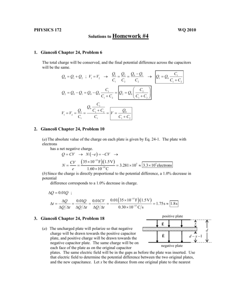
PHYSICS 172 WQ 2010 Solutions to Homework #4 1. Giancoli Chapter 24, Problem 6 The total charge will be conserved, and the final potential difference across the capacitors will be the same. Q0 Q1 Q2 ; V1 V2 Q2 Q0 Q1 Q0 Q0 V1 V2 Q1 C1 Q0 Q1 C1 Q2 C2 Q0 Q1 C2 C1 C1 C2 Q1 Q0 C1 C1 C2 C1 C2 C2 Q2 Q0 C1 C1 C2 C1 V Q0 C1 C2 2. Giancoli Chapter 24, Problem 10 (a) The absolute value of the charge on each plate is given by Eq. 24-1. The plate with electrons has a net negative charge. Q CV N e CV N CV 35 10 F 1.5V 3.281 10 15 5 3.3 105 electrons e 1.60 1019 C (b) Since the charge is directly proportional to the potential difference, a 1.0% decrease in potential difference corresponds to a 1.0% decrease in charge. Q 0.01Q ; t Q Q t 0.01Q Q t 0.01CV Q t 3. Giancoli Chapter 24, Problem 18 0.01 35 1015 F 1.5 V 0.30 10 15 Cs 1.75s 1.8s positive plate E x (a) The uncharged plate will polarize so that negative charge will be drawn towards the positive capacitor E d xl plate, and positive charge will be drawn towards the negative capacitor plate. The same charge will be on negative plate each face of the plate as on the original capacitor plates. The same electric field will be in the gaps as before the plate was inserted. Use that electric field to determine the potential difference between the two original plates, and the new capacitance. Let x be the distance from one original plate to the nearest d face of the sheet, and so d l x is the distance from the other original plate to the other face of the sheet. Q d l x Q Qx E ; V1 Ex ; V2 E d l x 0 A 0 A 0 A 0 V V1 V2 Qx A 0 Q d l x A 0 Q d l A 0 Q C C 0 A d l (b) Cinitial 0 A d ; Cfinal 0 A d l ; 0 Cfinal Cinitial A d d 1 d l 1.7 A d l d 0.40 d 0.60 0 d 4. Giancoli Chapter 24, Problem 24 The capacitors are in parallel, and so the potential is the same for each capacitor, and the total charge on the capacitors is the sum of the individual charges. We use Eqs. 24-1 and 242. Q1 C1V 0 A1 d1 V ; Q2 C2V 0 Qtotal Q1 Q2 Q3 0 A1 d1 V 0 A2 d2 A2 d2 V ; Q3 C3V 0 V 0 A3 d3 A3 d3 A1 d1 V 0 V 0 A2 d2 0 A3 V d3 A1 A A 0 0 2 0 3 V d1 d2 d3 A Q A A Cnet total 0 1 0 2 0 3 C1 C2 C3 V V d2 d3 d1 5. Giancoli Chapter 24, Problem 27 The maximum capacitance is found by connecting the capacitors in parallel. Cmax C1 C2 C3 3.6 109 F 5.8 109 F 1.00 108 F 1.94 108 F in parallel The minimum capacitance is found by connecting the capacitors in series. 1 Cmin 1 1 1 1 1 1 1 1.82 109 F in series 9 9 8 3.6 10 F 5.8 10 F 1.00 10 F C1 C2 C3 6. Giancoli Chapter 24, Problem 30 C1 and C2 are in series, so they both have the same charge. We then use that charge to find the voltage across each of C1 and C2. Then their combined voltage is the voltage across C3. The voltage across C3 is used to find the charge on C3. Q1 Q2 12.4 C ; V1 Q1 C1 12.4 C 16.0 F 0.775 V ; V2 Q2 C2 12.4 C 16.0 F 0.775 V V3 V1 V2 1.55 V ; Q3 C3V3 16.0 F 1.55 V 24.8C From the diagram, C4 must have the same charge as the sum of the charges on C1 and C3. Then the voltage across the entire combination is the sum of the voltages across C4 and C3. Q 37.2 C Q4 Q1 Q3 12.4 C 24.8C 37.2 C ; V4 4 1.31V C4 28.5 F Vab V4 V3 1.31V 1.55 V 2.86 V Here is a summary of all results. Q1 Q2 12.4 C ; Q3 24.8C ; Q4 37.2 C V1 V2 0.775 V ; V3 1.55 V ; V4 1.31V ; Vab 2.86 V 7. Giancoli Chapter 24, Problem 37 (a) The series capacitors add reciprocally, and then the parallel combination is found by adding linearly. 1 1 1 1 1 C C C3 C2C3 C Ceq C1 C1 3 2 C1 2 C1 C2 C3 C2 C3 C2C3 C2C3 C2C3 (b) For each capacitor, the charge is found by multiplying the capacitance times the voltage. For C1 , the full 35.0 V is across the capacitance, so Q1 C1V 24.0 106 F 35.0 V 8.40 104 C . The equivalent capacitance of the series combination of C 2 and C3 has the full 35.0 V across it, and the charge on the series combination is the same as the charge on each of the individual capacitors. 1 1 C 1 Ceq 3 C C 2 Qeq CeqV 1 3 24.0 10 F 35.0 V 2.80 10 6 4 C Q2 Q3 8. Giancoli Chapter 24, Problem 40 No two capacitors are in series or in parallel in the diagram, and so we may not simplify by that method. Instead use the hint as given in the problem. We consider point a as the higher voltage. The equivalent capacitance must satisfy Qtot CeqV . (a) The potential between a and b can be written in three ways. Alternate but equivalent expressions are shown in parentheses. V V2 V1 ; V V2 V3 V4 ; V V5 V4 V2 V3 V5 ; V3 V4 V1 There are also three independent charge relationships. Alternate but equivalent expressions are shown in parentheses. Convert the charge expressions to voltage – capacitance expression. Qtot Q2 Q5 ; Qtot Q4 Q1 ; Q2 Q1 Q3 Q4 Q3 Q5 CeqV C2V2 C5V5 ; CeqV C4V4 C1V1 ; C2V2 C1V1 C3V3 We have a set of six equations: V V2 V1 1 ; V V2 V3 V4 2 ; V V5 V4 3 CeqV C2V2 C5V5 4 ; CeqV C4V4 C1V1 5 ; C2V2 C1V1 C3V3 6 Solve for C eq as follows. From Eq. (1), V1 V V2 . Rewrite equations (5) and (6). V1 has been (i) eliminated. CeqV C4V4 C1V C1V2 5 ; C2V2 C1V C1V2 C3V3 6 From Eq. (3), V5 V V4 . Rewrite equation (4). V5 has been eliminated. (ii) CeqV C2V2 C5V C5V4 4 (iii) From Eq. (2), V3 V V2 V4 . Rewrite equation (6). V3 has been eliminated. C2V2 C1V C1V2 C3V C3V2 C3V4 6 C1 C2 C3 V2 C3V4 C1 C3 V 6 Here is the current set of equations. CeqV C2V2 C5V C5V4 4 CeqV C4V4 C1V C1V2 5 C1 C2 C3 V2 C3V4 C1 C3 V 6 (iv) From Eq. (4), V4 1 C5 C V 2 2 C5V CeqV . Rewrite equations (5) and (6). C5CeqV C4 C2V2 C5V CeqV C5C1V C5C1V2 5 C5 C1 C2 C3 V2 C3 C2V2 C5V CeqV C5 C1 C3 V 6 (v) C C 5 Group all terms by common voltage. C4Ceq C4C5 C5C1 V C4C2 C5C1 V2 5 eq C5 C1 C3 C3Ceq C3C5 V C5 C1 C2 C3 C3C2 V2 6 (vi) Divide the two equations to eliminate the voltages, and solve for the equivalent capacitance. C C C4 Ceq C4 C5 C5C1 C4C2 C5C1 C5 C1 C3 C3Ceq C3C5 C5 C1 C2 C3 C3C2 5 eq Ceq C1C2 C3 C1C2 C4 C1C2 C5 C1C3C5 C1C4 C5 C2 C3C4 C2 C4 C5 C3C4 C5 C1C3 C1C4 C1C5 C2 C3 C2 C4 C2C5 C3C4 C3C5 (b) Evaluate with the given data. Since all capacitances are in F, and the expression involves capacitance cubed terms divided by capacitance squared terms, the result will be in F. Ceq C1C2C3 C1C2C4 C1C2C5 C1C3C5 C1C4C5 C2C3C4 C2C4C5 C3C4C5 C1C3 C1C4 C1C5 C2C3 C2C4 C2C5 C3C4 C3C5 C1 C2 C3 C4 C5 C5 C3 C4 C4 C2C3 C2C5 C3C5 C1 C3 C4 C5 C2 C3 C4 C5 C3 C4 C5 4.5 8.0 17.0 4.512.5 8.0 8.0 4.5 8.0 4.5 4.5 4.5 F 4.517.0 8.0 17.0 4.512.5 6.0 F 9. Giancoli Chapter 24, Problem 48 (a) Before the capacitors are connected, the only stored energy is in the initially-charged capacitor. Use Eq. 24-5. U1 12 C1V02 1 2 2.20 10 F 12.0 V 6 2 1.584 104 J 1.58 10 4 J (b) The total charge available is the charge on the initial capacitor. The capacitance changes to the equivalent capacitance of the two capacitors in parallel. Q Q1 C1V0 ; Ceq C1 C2 ; U 2 1 2 Q2 Ceq 1 2 C12V02 C1 C2 2.20 10 F 12.0 V 5.70 10 F 6 1 2 2 2 6 6.114 105 J 6.11 10 5 J (c) U U 2 U1 6.114 10 5 J 1.584 10 4 J 9.73 10 5 J ¬ d 10. Giancoli Chapter 24, Problem 63 K x (a) We treat this system as two capacitors, one with a dielectric, x + and one without a dielectric. Both capacitors have their high voltage plates in contact and their low voltage plates in contact, so they are in parallel. Use Eq. 24-2 and 24-8 for the capacitance. Note that x is measured from the right edge of the capacitor, and is positive to the left in the diagram. C C1 C2 0 l l x d l2 x K 0 0 1 K 1 d d l lx (b) Both “capacitors” have the same potential difference, so use U 12 CV 2 . U 1 2 C1 C2 V02 0 l2 x 1 K 1 V02 2d l (c) We must be careful here. When the voltage across a capacitor is constant and a dielectric is inserted, charge flows from the battery to the capacitor. So the battery will lose energy and the capacitor gain energy as the dielectric is inserted. As in Example 24-10, we assume that work is done by an external agent Wnc in such a way that the dielectric has no kinetic energy. Then the work-energy principle (Chapter 8) can be expressed as Wnc U or dWnc dU . This is analogous to moving an object vertically at constant speed. To increase (decrease) the gravitational potential energy, positive (negative) work must be done by an outside, non-gravitational source. In this problem, the potential energy of the voltage source and the potential energy of the capacitor both change as x changes. Also note that the change in charge stored on the capacitor is the opposite of the change in charge stored in the voltage supply. dWnc dU dU cap dU battery Fnc dx d Fnc 12 V02 dC dx V0 dQbattery dx 12 V02 dC dx V0 1 2 CV02 d QbatteryV0 dQcap dx 12 V02 dC dx V02 dC dx 12 V02 dC dx l K 1 V l K 1 d l 2d Note that this force is in the opposite direction of dx, and so is to the right. Since this force is being applied to keep the dielectric from accelerating, there must be a force of equal magnitude to the left pulling on the dielectric. This force is due to the attraction of the charged plates and the induced charge on the dielectric. The magnitude and direction 12 V02 0 2 of this attractive force are 2 0 0 V02 0 l 2d K 1 , left .
