chapter 12: aeronautical charts and navigation
advertisement
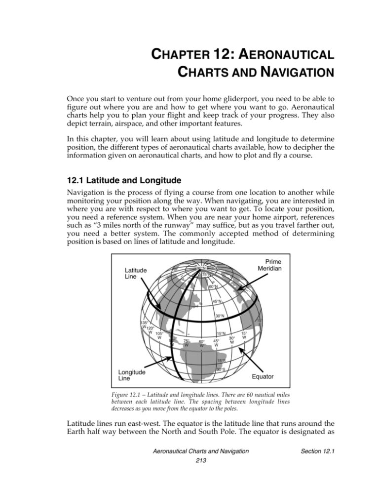
CHAPTER 12: AERONAUTICAL CHARTS AND NAVIGATION Once you start to venture out from your home gliderport, you need to be able to figure out where you are and how to get where you want to go. Aeronautical charts help you to plan your flight and keep track of your progress. They also depict terrain, airspace, and other important features. In this chapter, you will learn about using latitude and longitude to determine position, the different types of aeronautical charts available, how to decipher the information given on aeronautical charts, and how to plot and fly a course. 12.1 Latitude and Longitude Navigation is the process of flying a course from one location to another while monitoring your position along the way. When navigating, you are interested in where you are with respect to where you want to get. To locate your position, you need a reference system. When you are near your home airport, references such as “3 miles north of the runway” may suffice, but as you travel farther out, you need a better system. The commonly accepted method of determining position is based on lines of latitude and longitude. Figure 12.1 – Latitude and longitude lines. There are 60 nautical miles between each latitude line. The spacing between longitude lines decreases as you move from the equator to the poles. Latitude lines run east-west. The equator is the latitude line that runs around the Earth half way between the North and South Pole. The equator is designated as Aeronautical Charts and Navigation 213 Section 12.1 latitude 0°. Latitude is measured in degrees north or south of the equator, with the poles being 90°. Longitude lines, also called meridians, run north-south. Longitude is measured in degrees east or west of the prime meridian, the line of longitude that runs through Greenwich, England. Each degree of latitude or longitude is divided into 60 equal segments called minutes. Each minute can further be divided into 60 seconds. Minutes and seconds are sometimes written as just the minutes with decimals. For example, 41° 36’ 30” could also be written 41° 36.5’. Latitude and longitude lines are printed and labeled on all aeronautical charts. Figure 12.2 – Determining latitude and longitude. Note that the ticked lines are spaced at 30-minute (one-half degree) intervals. The location of any point on Earth can be specified by its latitude and longitude. In Figure 12.2, the airport shown is located at 36° 47.5’ N, 121° 38.0’ W. A common error in determining latitude and longitude is to misinterpret the 30minute lines as degree lines. Notice in the example above that the middle latitude line is 37°, the top one is 37° 30’, and the lower one is 36° 30‘. Also, remember that latitude increases to the north (in the Northern Hemisphere), and longitude increases to the west. Time Zones The meridians are also useful for designating time zones. A day is defined as the time required for the Earth to make one complete rotation of 360°. Since the day is divided into 24 hours, the Earth revolves at the rate of 15° an hour. Noon is the time when the sun is directly above a meridian, morning when it is east of it, and afternoon when it is west of it. Section 12.1 Aeronautical Charts and Navigation 214 The standard practice is to establish a time zone for each 15° of longitude. This makes a difference of exactly one hour between each zone. In the United States, there are four time zones: Eastern (75°), Central (90°), Mountain (105°), and Pacific (120°). The dividing lines are somewhat irregular because communities near the boundaries often find it more convenient to be on the same time as neighboring communities or trade centers. Figure 12.3 shows the time zones in the United States. When the sun is directly above the 90th meridian, it is noon Central Standard Time. At the same time, it will be 1 p.m. Eastern Standard Time, 11 a.m. Mountain Standard Time, and 10 a.m. Pacific Standard Time. When “daylight saving” time is in effect, generally between the last Sunday in April and the last Sunday in October, the sun is directly above the 75th meridian at noon, Central Daylight Time. Figure 12.3 – Time zones The change in time between zones must be taken into account during long flights, especially when on an eastbound flight that must be completed before dark. Remember, an hour is lost when flying eastward from one time zone to another, or perhaps even when flying from the western edge to the eastern edge of the same time zone. You should determine the time of sunset at the destination by consulting a flight service station (AFSS/FSS) or the National Weather Service (NWS) and take this into account when planning an eastbound flight. In most aviation operations, time is expressed in terms of the 24-hour clock. Air traffic control instructions, weather reports and broadcasts, and estimated times Aeronautical Charts and Navigation 215 Section 12.1 of arrival are all based on this system. For example, 9:00 a.m. is expressed as 0900, 1:30 p.m. is 1330, and 10:45 p.m. is 2245. Because a pilot may cross several time zones during a flight, for convenience, a standard time system has been adopted. It is called Universal Coordinated Time (UTC) and is often referred to as Zulu time. UTC is the time at the prime meridian passing through Greenwich, England. All time zones around the world are in reference to UTC. To convert to UTC, do the following: Eastern Standard Time Add 5 hours Central Standard Time Add 6 hours Mountain Standard Time Add 7 hours Pacific Standard Time Add 8 hours For daylight saving time, one hour should be subtracted from the calculated times. 12.2 VFR Aeronautical Charts Aeronautical charts are the “road maps” for a pilot flying under visual flight rules (VFR). These charts provide information that allows you to track your position and information that enhances safety. The charts most often used by glider pilots are: • Sectional charts • VFR terminal area charts • World aeronautical charts Aeronautical charts are maintained and published by the National Aeronautical Charting Office (NACO). They may be obtained directly from NACO or at most pilot shops. Sectionals Sectional charts are the most common charts used by glider pilots. The charts have a scale of 1:500,000 (1 inch = 6.86 nautical miles or approximately 8 statute miles), which allows relatively detailed information to be depicted on the chart. The charts provide an abundance of information, including airport data, navigational aids, airspace, and topography. For the continental U.S., sectionals are revised semiannually. Section 12.2 Aeronautical Charts and Navigation 216 Figure 12.4 – Sectional chart coverage Each sectional covers an area of roughly 1,000 square miles and is named for a major city within its area of coverage. VFR Terminal Area Charts (TAC) Visual flight rule terminal area charts are helpful when flying in or near Class B airspace. They have a scale of 1:250,000 (1 inch = 3.43 nautical miles or approximately 4 statute miles). These charts provide more detailed topographical information than sectional charts and are revised semiannually (except for several Alaskan and Caribbean charts). Areas covered by VFR terminal area charts are indicated on sectional charts by a quarter-inch white line labeled with the letters “TAC”. World Aeronautical Charts (WAC) World aeronautical charts depict land areas at a size and scale convenient for navigation by moderate speed aircraft. WACs can be very useful for planning or flying long cross-country flights that span two or more sectionals. WACs are produced at a scale of 1:1,000,000 (1 inch = 13.7 nautical miles or approximately 16 statute miles). They use the same symbols as sectionals and generally resemble them, except they show less detail due to the smaller scale. WACs are revised annually for the continental U.S. Aeronautical Charts and Navigation 217 Section 12.2 Figure 12.5 – WAC coverage Each WAC is referred to by a two-letter, two-digit code. 12.3 Reading Aeronautical Charts The descriptions and examples in this section are for sectional charts. However, TACs and WACs use similar conventions. The chart legend lists various aeronautical symbols as well as information concerning terrain and contour elevations. Physical Features The elevation and configuration of the Earth's surface are certainly of importance to pilots, as is the ability to determine their position with respect to clearly identifiable landmarks. Terrain Points of equal elevation are connected by lines called contour lines. On sectional charts, basic contours are spaced at 500-foot intervals. Intermediate contours may also be shown at 250-foot intervals in moderately level or gently rolling areas. Occasionally, auxiliary contours at 50, 100, 125, or 150-foot intervals may be used to portray smaller relief features in areas of relatively low relief. Section 12.3 Aeronautical Charts and Navigation 218
