Experiment 5 Tests On A Single Phase Transformer
advertisement
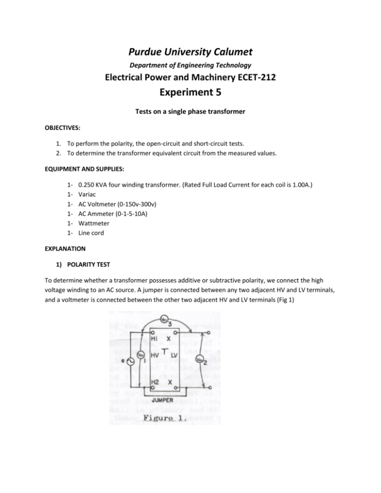
Purdue University Calumet Department of Engineering Technology Electrical Power and Machinery ECET-212 Experiment 5 Tests on a single phase transformer OBJECTIVES: 1. To perform the polarity, the open-circuit and short-circuit tests. 2. To determine the transformer equivalent circuit from the measured values. EQUIPMENT AND SUPPLIES: 111111- 0.250 KVA four winding transformer. (Rated Full Load Current for each coil is 1.00A.) Variac AC Voltmeter (0-150v-300v) AC Ammeter (0-1-5-10A) Wattmeter Line cord EXPLANATION 1) POLARITY TEST To determine whether a transformer possesses additive or subtractive polarity, we connect the high voltage winding to an AC source. A jumper is connected between any two adjacent HV and LV terminals, and a voltmeter is connected between the other two adjacent HV and LV terminals (Fig 1) If the voltmeter gives a higher reading than the source voltage, the polarity is additive. This tells us that H1 and X1 are diagonally opposite (Fig.2). On the other hand, if voltmeter reads less than the source voltage, the polarity is subtractive, and terminals H1 and X1 are adjacent. (Fig.3) In this polarity test, the jumper effectively connects the secondary voltage in series with the primary voltage. Consequently the secondary voltage either adds or subtracts from the primary voltage, depending on the polarity. In making the polarity test, an ordinary 120V, 60 Hz source can be connected to the HV winding, even though its rated voltage may be much higher. 2) OPEN CIRCUIT TEST The purpose of this test is to determine no-load loss or core loss and no-load current I0 which is helpful in finding Rm and Xm. One winding of the transformer- whichever is convenient but usually high voltage winding – is left open and the other is connected to a supply of normal voltage and frequency. A wattmeter, voltmeter and an ammeter are connected in the low-voltage winding (Fig.4)*. With the normal voltage applied to the primary, normal flux will be set up in the cores hence normal core losses will occur which are recorded by the wattmeter (Pm). As the primary no-load current Io is small (usually 2 to 10% of rated load current), copper loss is negligibly small in primary and nil in secondary (it being open). Hence, the wattmeter reading represents practically the core-loss under no load conditions (and which is the same for all loads, since the core flux is constant at all loads). *For the transformer used in the experiment the H1-H2 winding will be used. If a voltmeter is connected across the secondary winding, its reading will give the induced voltage in the secondary. This helps to find turns ratio “a”. The following calculations can then be made: Active power absorbed by core = Pm Apparent power absorbed by core = Sm = Ep Io Reactive power absorbed by core = Qm = √ (Sm 2 – Pm 2) Rm = Ep 2 / Pm Xm = Ep 2 / Qm a = N1 / N2 = Ep/Es 3) SHORT CIRCUIT TEST The purpose of this test is to determine copper loss at full load (and any desired load) and the equivalent resistance and leakage reactance of the transformer as referred to the winding in which the measuring instrument is placed. In this test, one winding, usually the low-voltage winding, is solidly short-circuited by a thick conductor as shown in Fig. 5. A low voltage (usually 5 to 10% of normal rated voltage) at rated frequency is applied to the primary and is cautiously increased till full-load current is flowing in the primary as indicated by the ammeter (Isc). Note, rated current flowing in the primary means rated current is also flowing in the secondary. Since, in this test, the applied voltage is a small percentage of the normal voltage, hence the mutual flux 0 produced is also a small percentage of its normal value. Hence core losses are very small with the result that the wattmeter reading represents the full load copper loss. The equivalent circuit of the transformer under shirt-circuited condition is shown in Fig. 6. If Esc is the voltage required to circulate rated currents, then Zp = Esc / Isc Rp = Psc / Isc 2 Xp = √(Zp 2 – Rp 2) PROCEDURE: A. POLARITY TEST Connect the transformer as shown in Fig. 1 to perform the polarity test and establish whether the transformer has an additive polarity, if the voltmeter reads more than the applied voltage. The transformer is wound for subtractive polarity if the voltmeter reads less than the applied voltage. B. OPEN CIRCUIT TEST Perform the open circuit test to determine the core loss for the transformer. 1. Set up the circuit as in Fig. 4. 2. Energize the circuit and adjust the variac for rated voltage across the primary winding of the transformer under test. 3. Measure I0, Pm and Ep. C. SHORT CIRCUIT TEST Perform the short circuit test to determine the copper losses for the transformer. 1. 2. 3. 4. 5. 6. Set up the circuit as in Fig.5. Short the other side X1 X2 with a solid wire. Make sure the Variac is at the zero volt position, then close the power switch. Slowly increase the primary voltage with the variac until rated current flows in the primary. Measure Psc, Esc and Isc. Calculate Rp and Xp. Draw the equivalent circuit of the transformer showing the values that were obtained from the previous parts. 7. Determine the per unit impedance of the transformer. 8. Identify the transformer used and document the transformer parameters for use in experiment #6. QUESTIONS 1. 2. 3. 4. 5. Does the core loss vary with the load? Why? Does the copper loss vary with the load? How? In the open circuit test, why the copper loss in the primary can be neglected? In the shirt circuit test, why can the core loss be neglected? Are the terms Rm and Xm significant when the transformer is loaded? Why? CONCLUSIONS:

