2. ceramics
advertisement
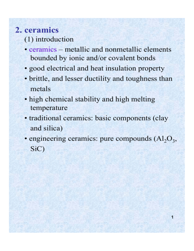
2. ceramics (1) introduction • ceramics – metallic and nonmetallic elements bounded by ionic and/or covalent bonds • good electrical and heat insulation property • brittle, and lesser ductility and toughness than metals • high chemical stability and high melting temperature • traditional ceramics: basic components (clay and silica) • engineering ceramics: pure compounds (Al2O3, SiC) 1 (2) ceramic crystal structures (a) ionic and covalent bonding in simple ceramics mixture of ionic and covalent types depends on electronegativity difference 2 (b) simple ionic arrangements • packing of ions depends upon (i) relative size of ions (ii) need to balance electron charges • if the anion does not touch the cation, then the arrangement is unstable coordination number – the number of anions that surround a central cation in an ionic solid radius ratio = rcation/ranion critical radius ratio for stability ex. calculate the critical radius r/R for the triangular coordination (CN = 3) R cos = ——— = 0.866 R+r 0.866R + 0.866r = R 0.866r = 0.134R r/R = 0.134/0.866 = 0.155 30o 3 ex. predict the coordination number for the ionic solids CsCl and NaCl r(Cs+) 0.170 nm ———— = ———— = 0.94 r(Cl ) 0.181 nm cubic coordination CN = 8 for CsCl r(Na+) 0.102 nm ———— = ———— = 0.56 r(Cl ) 0.181 nm octahedral coordination CN = 6 for NaCl 4 (c) cesium chloride crystal structure • CsCl is ionically bonded with radius ratio = 0.94 and CN = 8 • 8 Cl- ion surround a central Cs+ ion at the ( ½ , ½ , ½ ) position • CsBr, TlCl and TlBr have similar structure ex. calculate the ionic packing factor for CsCl (r(Cs+) = 0.170 nm, r(Cl-) = 0.181 nm) √3a = 2r + 2R = 2(0.170 + 0.181) = 0.502 nm a = 0.405 nm 4/3π [(0.170)3+(0.181)3] packing factor = ———————— (0.405)3 = 0.68 5 (d) sodium chloride crystal structure • highly ionically bonded with Na+ ions occupying octahedral sites between FCC Cl- ions and radius ratio = 0.56, CN = 6 • MgO, CaO, NiO and FeO have similar structures ex. calculate the density of NaCl from the crystal structure (r(Na+) = 0.102 nm, r(Cl-) = 0.181 nm) 4 Na+ and 4 Cl- ions per unit cell mass of a NaCl unit cell = 4 × (22.99 + 35.45) × 1.67 × 10-24 = 3.88 × 10⁻²² g 6 lattice constant a = 2 (R + r) = 2 (0.102 + 0.181) = 0.566 nm volume of unit cell = a3 = (0.566 × 10⁻⁷ cm)3 = 1.81 × 10⁻²² cm3 density = 3.88 × 10⁻²² g/1.81 × 10-22 cm = 2.16 g/cm3 ex. calculate the linear density of Ca2+ and O2in ions/nm in the [110] direction of CaO (r(Ca2+) = 0.106 nm, r(O2-) = 0.132 nm) a = 2(R + r) = 2(0.106 + 0.132) = 0.476 nm in [110] direction ρL = 2 O2- ions/ √2a = 2 O2- ions/ √2(0.476 nm) = 2.97 O2- ions/nm (2.97 Ca2+ ions/nm) ex. calculate the planar density of Ca2+ and O2- in ions/nm2 on (111) plane (111) plane contains 2 O2- (or 2 Ca2+) ions 1 √3 A = — (√2a)(—— a) 2 √2 = √3 a2/2 = 0.196 nm2 ρplanar = 2 O2- ions/ 0.196 nm2 = 10.2 O2- ions/nm72 (e) interstitial sites in FCC and HCP crystal lattices • octahedral interstitial sites – 6 nearest atoms or ions equidistant from central void • tetrahedral interstitial sites – 4 nearest atoms or ions equidistant from central void • there are 4 octahedral sites and 8 tetrahedral sites per unit cell of FCC 8 • location of interstitial sites octahedral sites tetrahedral sites • there is also the same number of octahedral interstitial sites as atoms in HCP unit cell and twice as many tetrahedral sites as atoms (f) zinc blende (ZnS) crystal structue • 4 zinc and 4 sulfur atoms • one type (Zn or S) occupies lattice points and another occupies interstitial sites of FCC unit cell. • S atoms (0,0,0) ( ½ ,½ ,0) ( ½ , 0, ½ ) (0, ½ , ½ ) Zn atoms ( ¾ ,¼ ,¼ ) ( ¼ ,¼ ,¾ ) 9 ( ¼ ,¾,¼ ) ( ¾ ,¾ ,¾ ) • tetrahedrally covalently bonded (87% covalent character) with CN = 8 • CdS, InAs, InSb and ZnSe have similar structures ex. calculate the density of zinc blende (r(Zn2+) = 0.060 nm, r(S2-) = 0.174 nm) 4 Zn2+ and 4 S2- ions per unit cell mass of unit cell = 4 (65.37 + 32.06) × 1.67 × 10-24 = 6.47 × 10⁻²² g lattice constant √3 a/4 = (R + r) a = 4 (R + r)/ √3 = 4(0.06 + 0.174)/√3 = 0.540 nm volume of unit cell = (5.40 × 10⁻⁸ cm)3 = 1.57 × 10⁻²² cm3 3 density = 6.47 × 10⁻²² g/1.57 × 10-22 cm3 = 4.12 g/cm 10 (g) calcium fluoride (CaF2) crystal structure • Ca2+ ions occupy the FCC lattice sites while F- ions are located at 8 tetrahedral sites • UO2, BaF2, PbMg2 have similar structures large number of unoccupied octahedral sites in UO2 allow it to be used as nuclear fuel fission products are accommodated in these vacant positions ex. calculate the density of UO2 (r(U4+) = 0.105 nm, r(O2-) = 0.132 nm) 4 U4+ and 8 O2- ions per unit cell mass of the unit cell = (4 × 238 + 8 × 16) × 1.67 × 10-24 = 1.794 × 10⁻²¹ g lattice constant √3a = 2 (2R + 2r) a= 4(R + r)/√3 = 4(0.105 + 0.132)/√3 = 0.5474 nm 11 -21 -8 3 3 density = 1.794 × 10 /(5.474 × 10 ) = 10.9 g/cm (h) antifluoride • anions occupy lattice points and cations occupy eight tetrahedral sites of FCC • examples – Li2O, Na2O, K2O, Mg2Si (i) corundum (Al2O3) crystal structure • oxygen ions in lattice points of HCP unit cell, 2 Al3+ ions in 2/3 octahedral sites for every 3 O2- ions • it leads to some distortion of structure (j) spinel (MgAl2O4) crystal structure • O2- ions form FCC lattice and Mg2+ and Al3+ ions occupy interstitial sites • these are nonmetallic magnetic materials 12 (k) perovskite (CaTiO3) crystal structure • Ca2+ and O2- ions form FCC unit cell Ca2+ ions occupy corners and O2- ions occupy face centers Ti4+ ions are at octahedral sites • other examples: BaTiO3, SrTiO3, CaZrO3, SrZrO3, LaAlO3 13 (l) carbon and its allotropes (i) graphite • layered structure with carbon atoms in hexagonal arrays • layers are bonded together by weak secondary bonds • free electrons can easily travel from one side to the other in the same layer • good lubricating properties (ii) diamond • the stiffest, hardest and least compressible material made by nature • synthetic diamonds are used as cutting tools, 14 coating, and abrasives (iii) buckminister fullerenes (buckyball) C60 • made of 12 pentagons and 20 hexagons • diameter of the C60 is 0.710 nm nanocluster • aggregate form of C60 has an FCC structure STM image (iv) carbon nanotubes • the most frequently encountered diameter is 1.4 nm, length can be in μm or even mm • single-wall nanotube (SWNT) and mutiwall nanotube (MWNT) can be synthesized • low density, high heat conductivity, high electron conductivity 15 (3) silicate structures basic structure • silicate (SiO44-) tetrahedron is building block • Si—O bond : 50% ionic and 50% covalent • SiO44- tetrahedrons are normally joined corner to corner and rarely edge to edge • many different types of silicate structures can be produced (a) island structure • positive ions bond with the oxygen of SiO44- tetrahedron such as (Mg, Fe)SiO4 (b) chain/ring structure • two corners of each SiO44- tetrahedron bonds with corners of other tetrahedron • chain (MgSiO3) or ring (Be3Al2(SiO3)6) structure with the unit formula of SiO32results 16 (c) sheet structure • three corners of same planes of silicate tetrahedron bonded to the corners of three other silicate tetrahedra • the unit chemical formula – Si2O52- • each tetrahedron has one unbounded oxygen and hence chains can bond with other type of sheets if the bondings are weak, sheets slide over each other easily 17 (d) silicate networks • silica – SiO2 network in which all four corners of the SiO44- tetrahedra share oxygen atoms • three basic structures – quartz, tridymite and cristobalite, the most stable forms of silica depend on the temperature range: low quartz < 573oC 573~867oC high quartz high tridymite 867~1470oC > 1710oC liquid • feldspars – infinite 3D networks, some Al3+ ions replace Si4+ ions, net negative charge is balanced by alkaline and alkaline ions (Na+, K+, Ca2+, Ba2+) fit into interstitial sites 18 19 (4) processing of ceramics produced by compacting powder or particles into shapes and heated to bond particles together three basic steps: (a) material preparation particles and other ingredients (binders and lubricants) are ground and blend wet or dry ex. spray-dried pellets of alumina ceramic (b) forming or casting • agglomerating particles formed in dry, plastic or liquid conditions • cold forming process is predominant • pressing, slip casting and extrusion are the common forming processes (i) dry pressing – simultaneous uniaxial compaction and shaping of power along with binder in a die wide variety of shapes can be formed 20 rapidly and accurately (ii) isolatic pressing – ceramic powder is loaded into a flexible, airtight container (bag) and pressure is applied outside the chamber with hydraulic fluid the force of applied pressure is uniform in all directions examples: spark plug insulators, carbide tools, crucibles, bearings (iii) hot pressing – combing the pressing and firing operations both uniaxial and isostatic method are 21 used (iv) slip casting – process that can cast ceramic shapes • powdered ceramic material and a liquid mixed to prepare a stable suspension (called slip) • slip is poured into porous mold and liquid portion is partially absorbed by mold layer of semi-hard material is formed against mold surface • excess slip is poured out of cavity or cast as solid • the material in mold is allowed to dry and then fired 22 (v) extrusion – single cross sections and hollow shapes of ceramics can be produced by extrusion • plastic ceramic material is forced through a hard steel or alloy die by a motor driven augur (c) thermal treatments drying – parts are dried before firing to remove water from ceramic body, • usually carried out at or below 100oC • organic binder can be removed by heating in the range of 200~300oC sintering – small particles are bonded together by solid state diffusion to produce dense, coherent product • carried out at higher temperature but below 23 melting point • as process proceeds, larger particles are formed at the expense of the smaller ones • the particles getting larger, the porosity of compacts decreases • the driving force for the process is the lowering of the surface energy of the system vitrification – during firing, glass phase liquefies and fills the pores upon cooling liquid phase of glass solidifies and a glass matrix that bonds the particles is24 formed (5) traditional and engineering ceramics (a) traditional ceramics made up of clay, silica and fledspar • clay: mainly hydrated aluminum silicates (Al2O3·SiO2·H2O) with small amount of other oxides provide workability and hardness • silica: provide better temperature resistance and high melting point refractory component of traditional ceramic • potash fledspar: the basic composition of K2O·Al2O3·6SiO2 makes a glass when ceramic is fired triaxial whiteware 25 silica-leucite-mullite ternary phase diagram what probably occurs during the firing of whiteware body 26 (b) engineering ceramics pure or nearly pure compounds of chiefly oxides, carbides, nitrides alumina (Al2O3) • used for refractory tubing, high-purity crucibles and park plug insulator material • commonly doped with MgO, cold pressed and sintered to form uniform grain structure used for electric application silicon nitride (Si3N4) • has the most useful combination of engineering properties • compact of Si powder is nitrided in a flow of nitrogen gas to produce microporous Si3N4 with moderate strength 27 • used for parts of advanced engines silicon carbide (SiC): • hard, refractory carbide with outstanding resistance to oxidation at high temperature • can be sintered at 2100oC • commonly used as reinforcement in composite materials zirconia (ZrO2) • polymorphic and transforms from tetragonal to monoclinic structure at 1170o and is subject to cracking • combined with 9% MgO can produce a partially stabilized zirconia (PSZ) ceramic with high fracture toughness 28 (6) mechanical properties of ceramics strength of ceramics vary greatly but they are generally brittle compressive strength is (5 to 10 times) higher than tensile strength (a) mechanism of deformation • covalently bonded ceramics: exhibit brittle fracture due to separation of electron-pair bonds without their subsequent reformation • ionically bonded ceramics: single crystal show considerable plastic deformation • polycrystalline ceramics are brittle ex. NaCl crystal slip of planes is rarely observed as same charges come into contact cracking occurs at grain boundaries 29 (b) factors affecting strength • failure occurs mainly from surface defects • pores gives rise to stress concentration and cracks • pores reduce effective cross-sectional area • flaw size is related to grain size • finer size ceramics have smaller flaws and hence are stronger. • composition, microstructure, surface condition, temperature and environment 30 also determine strength (c) toughness of ceramic materials • ceramics have low strength • research has been conducted to improve toughness • hot pressing with additives and reaction bonding improve toughness • KIC values obtained by four point bend test KIC = Y σf √π a σf : fracture stress (MPa) a : half size of target internal flaw Y : dimensionless constant ex. a silicon nitride ceramic has a strength of 300 MPa and a fracture toughness of 3.6 MPa√m, what is the large-size internal crack that the material can support without fracturing? (Y = 1) KIC = Y σf √π a = 3.6 MPa√m KIC2 (3.6 MPa√m) 2 -5 m a = ——— = ——————— = 4.58 × 10 π Y 2σf2 π (1)2 (300 Mpa)2 = 45.8 μm 31 the largest internal crack = 2a = 91.6 μm (d) transformation toughening of partially stabilized ZrO2 (PSZ) • transformation of zirconia combined with some other refractory oxides (MgO) can produce very high toughness ceramics. • ZrO2 exists in 3 structures monoclinic up to 11700C tetragonal 1170 – 23700C cubic above 23700C • if a mixture of ZrO2-9 mol% MgO is sintered at about 1800oC and rapidly cooled, it will be in metastable cubic structure 32 • if reheated to 1400oC and held for sufficient time tetragonal structure precipitates • under action of stress, this tetragonal structure transforms to monoclinic increasing volume and hence retarding crack growth (e) fatigue failure • fatigue fracture in ceramics is rare due to absence of plastic deformation • straight fatigue crack in has been reported in alumina after 79,000 compression cycles • ceramics are hard and can be used as abrasives 33 (7) thermal properties of ceramics • most ceramics have low thermal conductivities and are good thermal insulators • due to high heat resistance, many ceramics are used as industrial refractories 34 • Al2O3 and MgO are expensive and difficult to form into shapes, thus not used as refractories • most industrial refractories are made of mixture of ceramic compounds • important properties of ceramic refractory materials: (i) low- and high-temperature strengths, (ii) bulk density, and (iii) porosity • dense refractories with low porosity have high resistance to corrosion and erosion • a high amount of porosity is desirable for 35 insulating refractories (a) acidic refractories • silica refractories have high refractoriness, high mechanical strength and rigidity • fireclays – mixture of plastic fireclay, flint clay and clay grog • high-aluminum refractories contain 50-90% alumina and have higher fusion temperature (b) basic refractories • consists mainly of MgO, CaO, chrome ore • have bulk densities, high melting points and good resistance to chemical attack (c) insulation for space shuttle orbiter • about 70% of external surface is protected from heat by 24000 ceramic tiles made from a silica-fiber compound • high-temperature reusable-surface insulation (HRSI) – density is 4 kg/ft3 and can withstands temperatures as high as 1260oC 36 (8) glasses • inorganic products of fusion that has cooled to a rigid condition without crystallization • glass has amorphous structure • combination of transparency, hardness, sufficient strength, and corrosion resistance (a) glass transition temperature Tg • glass does not crystallize upon cooling, it transforms from rubbery material to rigid, brittle glassy state in a narrow temperature range 37 (b) structure of glasses • based on glass-forming oxide silica SiO2 fundamental subunit of glass is SiO44tetrahedron – Si4+ ion is covalently ionically bonded to four oxygen atoms • in cristobalite, Si-O tetrahedron are joined corner to corner to form long range order • in simple silica glass, tetrahedra are joined corner to corner to form loose network • glass modifying oxides network modifiers – oxides that breakup the glass network, added to glass to increase workability ex. Na2O, K2O, CaO, MgO oxygen atoms enter network other ions stay in interstices, by filling some interstices, these ions promote 38 crystallization of glass • intermediate oxides – cannot form glass network by themselves but can join into an existing network ex. Al2O3, lead oxide added to silica glass to obtain special properties (c) composition of glasses • soda lime glass – the most common glass (90%) composition : 71-73% SiO2, 12-14% Na2O, 10-12% CaO easier to form and used in flat glass and containers • borosilicate glass – replacement of alkali oxides by boric oxide in silica glass 39 network. known as Pyrex glass and is used for lab equipments and piping. • lead glass – lead oxide acts as network modifier and network former low melting point – used for solder sealing. used in radiation shields, optical glass and TV bulbs. 40 (d) viscous deformation of glasses behave as a viscous liquid above Tg and viscosity decreases with increase in temperature η = η0e+Q/RT Q : molar activation energy for viscous flow η : viscocity of glass (Pa·s) η0 : preexponential constant (Pa·s) R : gas constant 41 (i) working point (η = 103 Pa·s) – glass fabrication can be carried out (ii) softening point (η = 107 Pa·s) – glass flows under its own weight (iii) annealing point (η = 1012 Pa·s) – internal stresses can be relieved (iv) strain point (η = 1013.5 Pa·s) – glass is rigid below this point • interval between the annealing and strain points is commonly considered the annealing range of a glass ex. a 96% silica glass has a viscosity of 1013 P at its annealing point of 940oC and a viscosity of 108 P at its softening point 0f 1470oC, calculate the activation energy in kJ/mol for the viscous flow of this glass ηap = η0e+Q/RTap ηsp = η0e+Q/RTsp ηap Q 1 1 1013 5 —— = exp [ —— (—— - ——)] = —— = 10 ηsp 8.314 1213 1743 108 ln 105 = Q/8.314 (8.244 × 10⁻⁴ – 5.737 × 10⁻⁴) 11.5 = Q (3.01 × 10⁻⁵) Q = 3.82 × 10⁵ J/mol = 382 kJ/mol 42 (e) forming methods for glass • float-glass process – forming sheet and plate glass • blowing, pressing and casting of glass (f) tempered glass • glass is heated into near softening point and rapidly cooled • surface cools first and contracts causing tensile stresses in the interior and compressive stress on the surface • tempering treatment increases strength of 43 the glass (g) chemically strengthened glass special treatment increases chemical resistance of glasses ex. sodium aluminosilicate glasses are immersed in a bath of KNO3 at 50oC for 6~10 hours • large K+ ions are induced into surface causing compressive stress • compressive layer is much thinner than that in thermal tempering • used for supersonic aircraft glazing and ophthalmic lenses 44 (9) ceramics in biomedical applications • orthopedic implant • eyeglass • laboratory ware • thermometers • dental applications 45
