cutting force and snap
advertisement

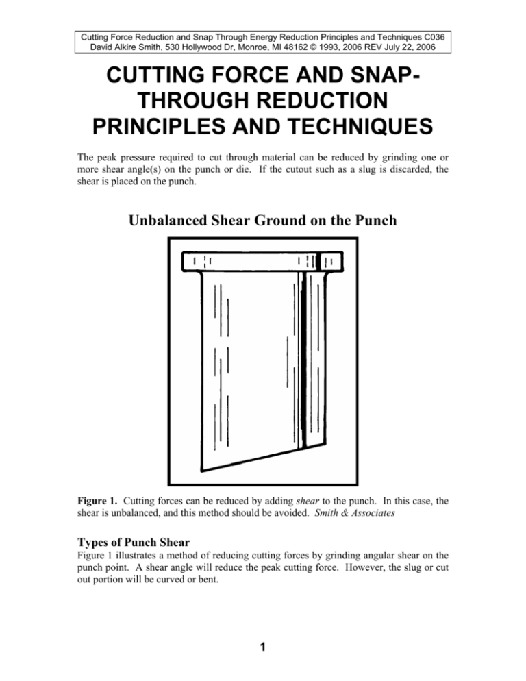
Cutting Force Reduction and Snap Through Energy Reduction Principles and Techniques C036 David Alkire Smith, 530 Hollywood Dr, Monroe, MI 48162 © 1993, 2006 REV July 22, 2006 CUTTING FORCE AND SNAPTHROUGH REDUCTION PRINCIPLES AND TECHNIQUES The peak pressure required to cut through material can be reduced by grinding one or more shear angle(s) on the punch or die. If the cutout such as a slug is discarded, the shear is placed on the punch. Unbalanced Shear Ground on the Punch Figure 1. Cutting forces can be reduced by adding shear to the punch. In this case, the shear is unbalanced, and this method should be avoided. Smith & Associates Types of Punch Shear Figure 1 illustrates a method of reducing cutting forces by grinding angular shear on the punch point. A shear angle will reduce the peak cutting force. However, the slug or cut out portion will be curved or bent. 1 Cutting Force Reduction and Snap Through Energy Reduction Principles and Techniques C036 David Alkire Smith, 530 Hollywood Dr, Monroe, MI 48162 © 1993, 2006 REV July 22, 2006 Simple Angular Shear A commonly practiced method is to grind a shear angle on a punch point. While this method will reduce peak punching forces, the shear is unbalanced, and will result in a side or lateral force. For thin stock, this method may be satisfactory. The punch and die guiding system must limit the side or lateral movement of the punch relative to the die. In no case should so much deflection occur that the punch and die come into direct contact. If the punched out portion is the part that must be flat, the shear must be ground on the die rather than the punch to limit part distortion. Any type of shear on the punch will curl or bend the cut out part. Balanced Vee Punch Shear Figure 2. The V-shear is balanced, which reduces the side loading on the die. This method is not suited for heavy punching applications because the punch may split in the middle. Smith & Associates Balanced Vee Shear Balanced Vee shear is an improvement. This method has two advantages. By balancing the load with symmetrical shear, lateral force is avoided. The hollow Vee designs also starts cutting at the edges of the slug and finally completes the fracture at the center. This may help reduce the spreading force on the die. 2 Cutting Force Reduction and Snap Through Energy Reduction Principles and Techniques C036 David Alkire Smith, 530 Hollywood Dr, Monroe, MI 48162 © 1993, 2006 REV July 22, 2006 A disadvantage of this design is that pressure is concentrated in the center of the punch. Cutting thick high-strength materials can develop sufficient tensile stress to cause this punch design to split at the center of the Vee. Balanced Pointed Shear Figure 3. Cutting forces can be reduced by adding balanced angular shear, which reduces the cutting load and the stress riser in the center of the punch shown in Figure 2. However the side-force on the die may be higher and need to be provided for in the sizing of the die block or button. Smith & Associates Balanced Pointed Shear For very heavy punching operations, a pointed punch, shown in Figure 3 can be used to reduce peak punching loads. If this design is used, the die block may need to be made larger to withstand any increase in lateral or side loads created by the bending-action of the slug. In both punch styles shown in Figures 2 and 3, the total energy required is greater due to the addition of bending forces. However, the peak force required is less, which is the goal of both force and snap through energy release reduction. 3 Cutting Force Reduction and Snap Through Energy Reduction Principles and Techniques C036 David Alkire Smith, 530 Hollywood Dr, Monroe, MI 48162 © 1993, 2006 REV July 22, 2006 Balanced Pointed Punch Shear in Heavy Hole Punching Figure 4. A chain side bar made of 0.625-inch (15.9-mm) thick SAE-ASTM 1039 finegrained carbon steel. A 6-inch (152.4-mm) scale shown in the photograph gives size comparison. Webster Industries/Smith & Associates Punching Thick Carbon-Steel, a Case Study Figure 4 is a photograph of a large chain side bar made of 0.625-inch (15.9-mm) thick AISI-SAE 1039 fine-grained carbon steel. A 6-inch (152.4-mm) scale is shown in the photograph for size comparison. Figure 5 is a close up view of the chain sidebar shown in Figure 4. Note the curvature in the slug. The punch has a pointed angular shear optimized for the material. 1 Waveform Signature Analysis of Punching Heavy Material Figure 6 illustrates the waveform signature of the stress-strain relationship when cutting off and piercing two holes in a chain side bar. The part is slightly smaller than the sidebar shown on Figures 4 and 5. The material is AISI-SAE 1039 fine grained steel 0.500-inch (12.7 mm) thick by 3.0-inches (76.2 mm) wide. 1 D. Smith, “Using Waveform Signature Analysis to Reduce Snap-Through Energy”, SME Technical Report MF90-11, Society of Manufacturing Engineers, Dearborn, Michigan, © 1990. The report has extensive background into the problem and solution including employee-training issues. 4 Cutting Force Reduction and Snap Through Energy Reduction Principles and Techniques C036 David Alkire Smith, 530 Hollywood Dr, Monroe, MI 48162 © 1993, 2006 REV July 22, 2006 The data was taken with a chart recorder speed of 200-mm (7.874 inches) per second. The vertical axis indicates stress or force. The horizontal axis represents time. Balanced Pointed Punch Shear—a Close up View Figure 5. A close up view of the chain sidebar shown in Figure 4. Note the curvature in the slug. The hole and slug were made with a punch having pointed angular shear optimized for the material. Webster Industries/Smith & Associates Importance of Timing of Break Through In timing punch entry or die shear, care must be given to provide for a gradual release of the force developed. With the exception of high-speed applications, a shock load is not normally generated by the impact of the punch on the stock. In fact, when the punch first contacts the stock, the initial work may be done by the kinetic energy of the slide. To complete the work, the flywheel supplies energy. As this occurs, the press members deflect. An analysis of the quantity of energy involved will show why a gradual reduction in cutting pressure prior to snap through is very important. Press Reverse Load Capacity A general rule for snap through or reverse load that a press can withstand without sustaining damage is 10% of rated press force or tonnage. Reverse loads significantly higher than 10% of total capacity may damage the machine. An especially critical part is the slide connection. The connection is the attachment of the pitman to the slide. Should the connection fail the slide may fall unexpectedly. Some presses are designed to withstand higher reverse loads. For example, Minster supplies presses on special order designed to withstand repeated reverse 50% reverse loads. 5 Cutting Force Reduction and Snap Through Energy Reduction Principles and Techniques C036 David Alkire Smith, 530 Hollywood Dr, Monroe, MI 48162 © 1993, 2006 REV July 22, 2006 Waveform Signature of Excessive Snap Through Figure 6. The actual waveform signature of a combined piercing and cut off operation having excessive snap through or reverse load. Webster Industries/Smith & Associates The press speed of the waveform signature in Figure 6 is 60 strokes per minute (SPM). Even at a chart speed of 200-mm (7.94 inches) per second, the waveform trace distance from initial contact of the punch on the work until it breaks through is very short. The portion of the waveform from initial punch contact to breakthrough occurs in 5 mm (0.20 inches) or 0.025 seconds. The punching waveform exhibits a sharp negative spike below the zero trace at break through. This is due to a sudden release of the energy stored in the press and die in the form of strains or deflection. A simplified mathematical analysis is possible. 2 Analysis of the Amount of Stored Energy The magnitude of the actual energy released increases as the square of the actual tonnage developed at the moment of final breakthrough. The actual energy is given by: FxD E = ——— (EQUATION 1) 2 2 D. Smith, Die Design Handbook, Section 4, Shear Action in Metal Cutting, The Society of Manufacturing Engineers, Dearborn, Michigan, 1990. Anthony Rante, PE. Manager of Mechanical Engineering, Danly Machine, Chicago, Illinois, is thanked for reviewing the Editor's formulas and examples. 6 Cutting Force Reduction and Snap Through Energy Reduction Principles and Techniques C036 David Alkire Smith, 530 Hollywood Dr, Monroe, MI 48162 © 1993, 2006 REV July 22, 2006 In this Equation: F = Pressure at moment of breakthrough in short tons. (lbf X 2,000) D = Amount of total deflection in inches. E times 166.7 = Energy in foot-pounds Or: F = Pressure at moment of breakthrough in Metric-tons (kgf X 1000). D = Amount of total deflection in Millimeters. E = 9.807 = Energy in Joules or WattSeconds Note: (1 Foot Pound = 1.356 Joules or Watt-Seconds) (1 Joule or Watt Second = 0.7376 Foot Pounds) (1 Inch-Ton = 166.7 Foot-Pounds) Simplified Square-Law Relationship Example An example using American units: if 400 tons resulted in 0.080-inch total deflection to cut through a thick steel blank, the energy released at snap through, from the formula, is 2667 foot pounds. Careful timing of the cutting sequence results in a reduction of the tonnage at the moment of snap through to 200 tons, the reduction in shock and noise is dramatic. This is because half the tonnage produces only half as much deflection or .040-inch. The resultant snap through energy is only 667 foot-pounds or one-fourth the former value. Actual Die Timing Improvement Timing shear and punch entry sequences to provide a gradual release of force prior to snap through is a straightforward way to reduce the shock and noise associated with this problem. The simplified analysis of the square-law relationship can be applied to our case study. A 300-ton (2,669-kN.) straightside press was used for this operation. The allowable reverse load is 30 tons (267 KN.). Point (A) of Figure 6 illustrates a peak load of 191 tons (1,699 kn.), which is well within press capacity. 7 Cutting Force Reduction and Snap Through Energy Reduction Principles and Techniques C036 David Alkire Smith, 530 Hollywood Dr, Monroe, MI 48162 © 1993, 2006 REV July 22, 2006 The reverse load (B) is 87 tons (774 kn.), which is nearly three times the allowable amount. The die was immediately taken to the repair bench and one punch shortened 0.312-inch (7.92 mm). Balanced angular shear was ground on the punches. Balanced shear was also ground on the parting punch. Figure 7 illustrates the improvement achieved by modifying the tool. The peak tonnage was reduced to 82.8 tons (737 kn.), which is less than half the initial value. The reverse load was reduced to 22 tons (196 kn.) or about one fourth the former values. Waveform Signature after Die Timing Improvement Figure 7. Waveform signature of the operation illustrated in Figure 6 after modifying the die by adding timing and balanced shear. Webster Industries/Smith & Associates Timing Results Agree With Square Law Formula This and the documented results of many other tests show snap through reductions conforming closely to the square law formula. Simply stated, if the amount of force or tonnage released at the moment of punch breakthrough can be reduced by one-half, the amount of stored energy, which causes snap through problems, will be reduced to onefourth the former magnitude. Waveform Signature of Combined Cutting and Bending Figure 8 illustrates the waveform signature of a combined punching, cutting off and joggle bending operation. Here, AISI-SAE 1039 steel 0.500-inch (12.7 mm) thick by 2.000-inch (50.8 mm) wide has two holes punched, and a 0.562-inch (14.27 mm) joggle formed. The part, an engineering class chain sidebar, is also cut off in this combined operation. The die is correctly timed. The snap through energy release is well below10% capacity of the 300 ton (2,669 kn.) straightside press was used for this operation 8 Cutting Force Reduction and Snap Through Energy Reduction Principles and Techniques C036 David Alkire Smith, 530 Hollywood Dr, Monroe, MI 48162 © 1993, 2006 REV July 22, 2006 Waveform Signature of Combined Cutting and Bending Figure 8. The waveform signature of a combined punching, cut off, and joggle bending operation: the part, an engineering class chain side bar, is also cut off in this combined operation. Webster Industries/Smith & Associates Providing Angular Shear on the Die All types of shear ground on the punches will result in curled or bend slugs. If the slug is the part, this may be unacceptable. In such cases, angular shear may be provided on the die. Distortion of the scrap skeleton is usually not a concern. The goal is to produce parts that are flat. In the die shown in Figure 9, flat areas around the corners at (D) provide a level support for the stock, and prevent slippage at the start of punch engagement. With the amount of shear (B) and angle of shear (A), cutting progresses from the outside corners to the center, producing a flat blank. As a rule, the amount of shear (B) is approximately one to three times stock thickness. Cutting Die Timing In addition to providing angular shear on the punch and or die, the entry of individual punches may be timed to reduce cutting forces. In the majority of cases, the punches penetrate the stock one-third of stock thickness when fracture occurs. Therefore, the entry of the punches is usually stepped in increments of approximately one-third stock thickness. In many cases, optimizing punch and die shear, together with stepping punch entry, can reduce peak cutting forces one-half to two-thirds the untimed value. It is important to note that the total flywheel energy required per stroke is not reduced. The process of optimizing cutting forces can be aided by force monitoring and waveform signature analysis. These methods are valuable process control tools. 9 Cutting Force Reduction and Snap Through Energy Reduction Principles and Techniques C036 David Alkire Smith, 530 Hollywood Dr, Monroe, MI 48162 © 1993, 2006 REV July 22, 2006 Providing Angular Shear on the Die Figure 9. Concave shear applied to the face of the die: the cutting progresses from the outside to the center, leaving a flat blank.3 Record Keeping of Die Timing It is very important to maintain records of the optimum die timing for each job. This information will save trial-and-error work when the die is resharpened. Proven timing data is also invaluable in avoiding trial and error adjustment of new dies. NOTES: _____________________________________________________ _____________________________________________________________ 3 D. Smith, Die Design Handbook, Section 4, Shear action in Metal Cutting, The Society of Manufacturing Engineers, Dearborn, Michigan, © 1990. 10


