Universality of Tip Singularity Formation in Freezing Water Drops
advertisement
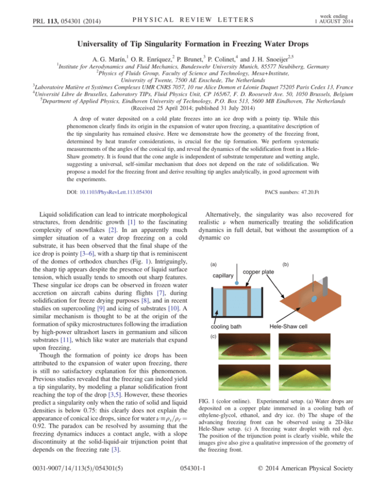
PRL 113, 054301 (2014) week ending 1 AUGUST 2014 PHYSICAL REVIEW LETTERS Universality of Tip Singularity Formation in Freezing Water Drops 1 A. G. Marín,1 O. R. Enríquez,2 P. Brunet,3 P. Colinet,4 and J. H. Snoeijer2,5 Institute for Aerodynamics and Fluid Mechanics, Bundeswehr University Munich, 85577 Neubiberg, Germany 2 Physics of Fluids Group, Faculty of Science and Technology, Mesa+Institute, University of Twente, 7500 AE Enschede, The Netherlands 3 Laboratoire Matière et Systèmes Complexes UMR CNRS 7057, 10 rue Alice Domon et Léonie Duquet 75205 Paris Cedex 13, France 4 Université Libre de Bruxelles, Laboratory TIPs, Fluid Physics Unit, CP 165/67, F. D. Roosevelt Ave. 50, 1050 Brussels, Belgium 5 Department of Applied Physics, Eindhoven University of Technology, P.O. Box 513, 5600 MB Eindhoven, The Netherlands (Received 25 April 2014; published 31 July 2014) A drop of water deposited on a cold plate freezes into an ice drop with a pointy tip. While this phenomenon clearly finds its origin in the expansion of water upon freezing, a quantitative description of the tip singularity has remained elusive. Here we demonstrate how the geometry of the freezing front, determined by heat transfer considerations, is crucial for the tip formation. We perform systematic measurements of the angles of the conical tip, and reveal the dynamics of the solidification front in a HeleShaw geometry. It is found that the cone angle is independent of substrate temperature and wetting angle, suggesting a universal, self-similar mechanism that does not depend on the rate of solidification. We propose a model for the freezing front and derive resulting tip angles analytically, in good agreement with the experiments. DOI: 10.1103/PhysRevLett.113.054301 PACS numbers: 47.20.Ft Liquid solidification can lead to intricate morphological structures, from dendritic growth [1] to the fascinating complexity of snowflakes [2]. In an apparently much simpler situation of a water drop freezing on a cold substrate, it has been observed that the final shape of the ice drop is pointy [3–6], with a sharp tip that is reminiscent of the domes of orthodox churches (Fig. 1). Intriguingly, the sharp tip appears despite the presence of liquid surface tension, which usually tends to smooth out sharp features. These singular ice drops can be observed in frozen water accretion on aircraft cabins during flights [7], during solidification for freeze drying purposes [8], and in recent studies on supercooling [9] and icing of substrates [10]. A similar mechanism is thought to be at the origin of the formation of spiky microstructures following the irradiation by high-power ultrashort lasers in germanium and silicon substrates [11], which like water are materials that expand upon freezing. Though the formation of pointy ice drops has been attributed to the expansion of water upon freezing, there is still no satisfactory explanation for this phenomenon. Previous studies revealed that the freezing can indeed yield a tip singularity, by modeling a planar solidification front reaching the top of the drop [3,5]. However, these theories predict a singularity only when the ratio of solid and liquid densities is below 0.75: this clearly does not explain the appearance of conical ice drops, since for water ν≡ρs =ρl ¼ 0.92. The paradox can be resolved by assuming that the freezing dynamics induces a contact angle, with a slope discontinuity at the solid-liquid-air trijunction point that depends on the freezing rate [3]. 0031-9007=14=113(5)=054301(5) Alternatively, the singularity was also recovered for realistic ν when numerically treating the solidification dynamics in full detail, but without the assumption of a dynamic co FIG. 1 (color online). Experimental setup. (a) Water drops are deposited on a copper plate immersed in a cooling bath of ethylene-glycol, ethanol, and dry ice. (b) The shape of the advancing freezing front can be observed using a 2D-like Hele-Shaw setup. (c) A freezing water droplet with red dye. The position of the trijunction point is clearly visible, while the images give also give a qualitative impression of the geometry of the freezing front. 054301-1 © 2014 American Physical Society PRL 113, 054301 (2014) PHYSICAL REVIEW LETTERS ntact angle [4,12]. The true mechanism behind the tip singularity has therefore remained elusive, in particular since there is a lack of systematic experiments to which any of the theories can be compared. In this Letter we reveal that the geometry of the freezing front, essentially determined by the final stages of a quasisteady heat transfer problem, is responsible for the formation of pointy ice drops. First, we experimentally show that the cone angles at the tip are universal, and do not depend on the substrate temperature, excluding the influence of the solidification rate. Next, we reveal the boundary conditions of the solidification front by tracking the freezing process in a Hele-Shaw geometry. It is found experimentally, and explained theoretically from heat conduction, that the front develops a spherical shape that ends perpendicularly to the solid-air interface. Taking this into account into the mass balance during solidification, we then show how the singularity emerges for any density ratio ν < 1. The theory predicts a cone angle α ¼ 131° for water drops [α defined in Fig. 1(c)], which falls within the range of experimental observations. Experiments.—Droplets of pure water (milli-Q, degassed) were frozen on a copper structure that is partially immersed in a cooling bath composed of ethylene-glycol, ethanol, and dry ice [Fig. 1(a)]. With this mixture, the temperature can be controlled in the range −78 to −17 °C by modifying the volume fraction of the two liquids [13]. Droplets of volume 4–8 μl were deposited using a syringe pump (Harvard Apparatus PHD ULTRA) and a 200 μm capillary. The temperature on the plate was measured near the droplet using a thermocouple. We focus here on temperatures above −44 °C, for which reproducible experiments could be performed. At lower temperatures nondirectional freezing and multiple freezing fronts appear. week ending 1 AUGUST 2014 The freezing process was recorded, using a PCO camera (Sensicam QE), a long distance microscope (Edmund Optics VZM1000), and diffused back lighting, until the tip was formed. We extracted the final shape of the drops through image analysis and fitted third-order polynomials to the left-hand and right-hand regions close to the tip. The angle of the tip is then computed as the intersecting angle of the polynomials, with an experimental error bar of 5° on average. The total time for the solidification is on the order of 1 sec for the coldest cases and 10 sec for the warmest. Importantly, the liquid near the contact line freezes long before reaching the equilibrium contact angle, so that different contact angles can be achieved by varying the height of deposition. This results in drops of different aspect ratio H=R, where H is defined as the final height of the ice drop and R the radius of the wetted area [see Fig 2(a) for geometric definitions and Fig. 2(b) for typical droplet shapes]. Various movies of the freezing process can be found as Supplemental Material [14]. Figure 2(b) shows typical shapes of ice drops, as obtained for different temperatures and contact angles. Despite the large disparity of drop shapes, the formation of the tip singularity appears to be independent of contact angle and substrate temperature. This can be inferred from Fig. 2(c), where we report the cone angle α for more than 200 experiments, carried out at different temperatures (horizontal axis) and for different aspect ratios (upward or downward symbols). All measurements fall within a well-defined range of tip angles, characterized by an average and standard deviation α ¼ 139° 8°. The data give no evidence for any correlation of α with temperature and aspect ratio. The experiments thus show that the tip formation is not influenced by global geometry of the drop, FIG. 2 (color online). Tip formation on freezing drops. (a) Sketch of the geometry during the final stages of the freezing process. θ is the angle formed by the liquid interface with the horizontal, ϕ is that formed by the solid-frozen interface with the horizontal, and α is the final tip angle. The drop radius R, and the “downward volume” V d are also defined. (b) Drops with different contact angles (i.e., aspect ratios) are achieved by changing the deposition height, at different temperatures. (c) Measurement of the tip angle α for the full range of temperatures explored. Base-down triangles represent data from droplets at high contact angles and therefore a height-to-radius aspect ratio H=R > 1. Base-up triangles represent drops with low contact angle characterized by aspect ratios H=R < 1. We find no systematic dependence of α with global drop shape and substrate temperature. The gray line indicates the theoretical prediction (4). 054301-2 PRL 113, 054301 (2014) PHYSICAL REVIEW LETTERS or by the rate at which the solidification occurs—the latter suggesting that the singularity is the outcome of a quasistatic process. The observed variability in α is beyond the accuracy of the measurement, and appears to be due to the conditions in which the experiments were performed, i.e., with the droplet exposed to air currents and vapor from the cooling bath. Freezing front.—To obtain further insight in the tip formation, we next investigate the shape of the solidification front. The still images in Fig. 1(c) suggest that the front does not remain planar, as was also discussed in Refs. [15,16]. However, in order to achieve quantitative access to the advancing front, we constructed a Hele-Shaw cell with two microscope slides separated by a 1 mm spacer [Fig. 1(b)]. The cell was placed on the copper plate and the capillary carefully maneuvered between the walls. The gap is wide enough for the drop to form a conical tip, but this is not always visible due to the presence of a wetting meniscus. To minimize image distortion due to this meniscus, the glass is treated such that the wetting contact angle ≈ 90°. This gives a clear view on the quasi-twodimensional freezing process—typical videos can be found in the Supplemental Material [14]. Figure 3(a) shows that the solidification front in the Hele-Shaw cell grows towards the top of the drop in a similar fashion to the unconfined experiment, although the time scale of the process is a bit faster. In the first instants of the process, vapor condensates on the glass slides resulting in a “frost halo” [9] around the drop. Such an event occurs week ending 1 AUGUST 2014 simultaneously as the partial and kinetically controlled recalescent freezing [17], also visible in Fig. 3(a) as a brighter area above the freezing front. Our prime interest here is to extract quantitative information on the geometry of the freezing front. The front shown in Fig. 3(a) has a convex shape at the early stage of the freezing, while at the last stages the curvature it is inverted towards a concave geometry. Interestingly, these profiles closely resemble two-dimensional numerical simulations [4]. At all times, the experimentally observed freezing front appears to be perpendicular to the ice-air interface. This is confirmed in Fig. 3(c), where we present the angle γ ¼ θ þ ϕ defined in Fig. 3(b), as a function of the height z of the trijunction point. The red line corresponds to the average over 20 experiments, performed at temperatures ranging from −30 to −15 °C. We find that the front is nearly perpendicular during the entire experiment. During the final stages we find an average and standard deviation γ ¼ 87° 8°. Heat-transfer-limited self-similar freezing dynamics.— Coming back to the axisymmetric case we now derive the shape of the solid-liquid front from the heat transfer in the late stages of the freezing process [cf. Fig. 2(a)]. We neglect any small-scale kinetic undercooling or Gibbs-Thomson effect (as considered, e.g., in Ref. [12]), such that the front here always remains at the equilibrium melting temperature T m . As the air surrounding the drop has a much smaller thermal conductivity than the solid (and the liquid), the latent heat released by the advancing front must be FIG. 3 (color online). Freezing experiments with droplets sandwiched in a Hele-Shaw cell. (a) Evolution of the freezing front (green line) in different stages of the process. (b) Sketch and definitions of angles and distances. (c) Front-to-interface angle γ plotted against the relative height of the freezing front z=H. Within experimental variations, we find γ ≈ 90°. 054301-3 PRL 113, 054301 (2014) week ending 1 AUGUST 2014 PHYSICAL REVIEW LETTERS evacuated via the solid, while the liquid remains at uniform temperature T m . The fact that heat cannot cross the solid-air boundary has an important consequence: it implies that the isotherms, in particular the freezing front at T m , are locally perpendicular to the solid-air boundary, i.e., γ ¼ 90°. This simple argument is in good agreement with the Hele-Shaw cell experiments, even though heat transfer via the glass slides might not be entirely negligible there. The final stages of the heat transfer are expected to be self-similar. Namely, the angle γ made by the front with the external surface remains approximately constant, and the freezing is characterized by a single length scale r, the radius at the triple junction [Fig. 2(b)]. Based on this length, one can derive a scaling law for the normal velocity vn of the front, which is proportional to the rate at which latent heat released by the front is evacuated. This gives vn ∼ −dr=dt∼ λs δT=ρs Lm r, where λs is the solid thermal conductivity, Lm is the latent heat of melting, and the undercooling δT ¼ T m − T. Here we assumed that the heat transfer process in the solid is quasisteady, i.e., that the time scale of front motion r=vn is much larger than the thermal diffusion time scale r2 =κs , where κs is the thermal diffusivity of the solid. Taking into account that κ s ¼ λs =ρs cp;s , where cp;s is the thermal capacity of the solid, this is equivalent to assuming that the Stefan number S ¼ cp;s δT=Lm is small [4]. Actually, we find S ¼ 0.27 for the maximal value of δT ¼ 44 K in our experiments, such that this quasisteadiness assumption is sufficiently accurate here [as also confirmed in Fig. 2(c)]. Note that solving the above energy balance for r leads to a classical r2 law; i.e., r2 decreases linearly with time during tip formation. The above theory also provides the self-similar shape of the freezing front, which is crucial for understanding the tip formation. The heat transfer problem amounts to solving ∇2 T ¼ 0 in the solid, with the boundary condition that the isotherms make an angle γ ¼ 90°. When the solid approaches a conical shape, the resulting isotherms are portions of concentric spheres centered at the final cone tip [Fig. 2(a)]. The two-dimensional equivalent is that the freezing front is a portion of a circle—in good agreement with the concave shape in the final stage [Fig. 3(a)]. This solution is stable with respect to dendrite formation given that cooling is from the solid side [1]. Hence, the front will remain spherical during the self-similar final stages of tip formation. Geometric theory for tip formation.—The results above point towards a scenario where the tip is formed by a quasistatic mechanism. Based on this, we propose a model in the spirit of Ref. [3], but taking into account the selfsimilar spherical geometry of the freezing front. The starting point is mass conservation d ðV þ νV s Þ ¼ 0; dz l ð1Þ here expressed in terms of liquid and solid volumes V l;s and density ratio ν. Since temporal dynamics is unimportant, the conservation law has been written in terms of a derivative with respect to z, the height of the trijunction. The total liquid volume can be decomposed into a spherical cap of angle θ and a downward volume V d [cf. Fig. 2(a)]. The liquid and solid volumes then are V l ¼ r3 fðθÞ þ V d ; Z V s ¼ −V d þ 0 z dz0 πrðz0 Þ2 ; ð2Þ where rðzÞ and θðzÞ are the local radius and angle of the frozen drop, and the geometry of a spherical cap gives π 2–3 cos θ þ cos3 θ fðθÞ ¼ : 3 sin3 θ ð3Þ Closing the problem requires an expression for V d, which in general implies a full solution of the solidification front. For the final stages, however, we can take advantage of our previous observation that the front develops a spherical shape with downward angle ϕ ¼ γ − θ, such that V d ¼ r3 fðγ − θÞ. With this, and taking into account that dr=dz ¼ −1= tan θ, Eqs. (1)–(3) give a closed set of equations for rðzÞ, indeed predicting a sharp tip as r → 0 [18]. At the singularity, θ obeys π fðγ − θÞ þ fðθÞ ¼ ν fðγ − θÞ þ tan θ ; 3 ð4Þ from which we can infer α ¼ π − 2θ, for any density ratio. The central result of this analysis is that, combined with our result that γ ¼ 90°, Eq. (4) gives a parameter-free prediction for the tip angle of ice drops: α ¼ 131°. This is consistent with our experimental observation α ¼ 139° 8°, though most experiments are slightly above the theoretical prediction. We tentatively attribute the experimentally observed variability in the cone angle to variations of γ. Inserting the γ variations measured in the Hele-Shaw cell in Eq. (4) indeed gives α ¼ 133° 5°, in close agreement with experiments. Equation (4) has an elegant interpretation in terms of the volumes before and after freezing. After multiplication by r3, the left-hand side represents the unfrozen liquid volume, consisting of two spherical caps. This mass is to be transformed into ice, where due to the expansion factor ν the upward liquid sphere is transformed into a cone of volume ðπ=3Þr3 tan θ. The tip angle is thus determined from purely geometrical considerations. Interestingly, the model does not display a critical density ratio: a tip is formed even for 0 < 1 − ν ≪ 1. This can be seen by expansion of Eq. (4), yielding a nonzero angle θ ¼ ð12=πÞfðγÞð1 − νÞ, in radians. This is in marked contrast with the model where the solidification front was assumed 054301-4 PRL 113, 054301 (2014) PHYSICAL REVIEW LETTERS planar [3,5], which predicted tip formation only for ν below a critical value 3=4. Outlook.—This offers a fundamentally new view of freezing phenomena near free surfaces, valid beyond the ice-cone formation studied here: our findings provide the first direct measurement of the boundary condition for the freezing front, and highlight that geometric aspects are more critical than dynamical effects. The confinement of heat transfer within the solid-liquid system is a generic feature of solidification near free surfaces. The results are therefore expected to have impact on a broad variety of applications, such as icing, drop impact on cold surfaces, and solidification during 3D printing. A. G. M. and O. R. E. contributed equally to the Letter and their names in the author list are interchangeable. We thank Koen Winkels for many discussions. J. H. S. acknowledges financial support from NWO through VIDI Grant No. 11304. P. C. acknowledges financial support from FRS-FNRS and BELSPO (IAP 7/38 μ-MAST). [1] M. E. Glicksman, Principles of Solidification (Springer, New York, 2002). [2] K. G. Libbrecht, Rep. Prog. Phys. 68, 855 (2005). [3] D. M. Anderson, M. G. Worster, and S. H. Davis, J. Cryst. Growth 163, 329 (1996). week ending 1 AUGUST 2014 [4] V. S. Ajaev and S. H. Davis, J. Comput. Phys. 187, 492 (2003). [5] J. H. Snoeijer and P. Brunet, Am. J. Phys. 80, 764 (2012). [6] O. R. Enriquez, A. G. Marin, K. G. Winkels, and J. H. Snoeijer, Phys. Fluids 24, 091102 (2012). [7] See, for example, SKYbrary, “In-Flight Icing,” http://www .skybrary.aero/index.php/In‑Flight_Icing. [8] J. D. Mellor et al., Fundamentals of Freeze-Drying (Academic Press, London, 1978). [9] S. Jung, M. K. Tiwari, and D. Poulikakos, Proc. Natl. Acad. Sci. U.S.A. 109, 16073 (2012). [10] S. Jung, M. Dorrestijn, D. Raps, A. Das, C. M. Megaridis, and D. Poulikakos, Langmuir 27, 3059 (2011). [11] K. W. Kolasinski, Curr. Opin. Solid State Mater. Sci. 11. 76 (2007). [12] V. S. Ajaev and S. H. Davis, J. Cryst. Growth 264, 452 (2004). [13] C. M. Jensen and D. W. Lee, J. Chem. Educ. 77, 629 (2000). [14] See Supplemental Material at http://link.aps.org/ supplemental/10.1103/PhysRevLett.113.054301 for several experimental videos of the freezing drops. [15] M. Nauenberg, Am. J. Phys. 81, 150 (2013). [16] J. H. Snoeijer and P. Brunet, Am. J. Phys. 81, 151 (2013). [17] F. Tavakoli, A. Sarkissians, and P. Kavehpour, arXiv:1210.3759. [18] The tip formation is obtained by taking r → 0. In this limit, the asymptotic solution is of the form θðrÞ − θcone ¼ Arb , where the sought for cone angle θcone is given by condition (4). 054301-5
