Design and implementation of a teleprotection system with digital
advertisement

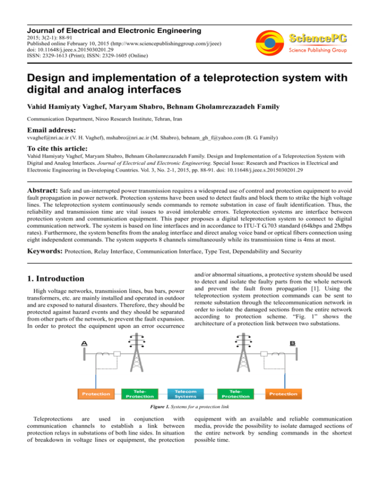
Journal of Electrical and Electronic Engineering 2015; 3(2-1): 88-91 Published online February 10, 2015 (http://www.sciencepublishinggroup.com/j/jeee) doi: 10.11648/j.jeee.s.2015030201.29 ISSN: 2329-1613 (Print); ISSN: 2329-1605 (Online) Design and implementation of a teleprotection system with digital and analog interfaces Vahid Hamiyaty Vaghef, Maryam Shabro, Behnam Gholamrezazadeh Family Communication Department, Niroo Research Institute, Tehran, Iran Email address: vvaghef@nri.ac.ir (V. H. Vaghef), mshabro@nri.ac.ir (M. Shabro), behnam_gh_f@yahoo.com (B. G. Family) To cite this article: Vahid Hamiyaty Vaghef, Maryam Shabro, Behnam Gholamrezazadeh Family. Design and Implementation of a Teleprotection System with Digital and Analog Interfaces. Journal of Electrical and Electronic Engineering. Special Issue: Research and Practices in Electrical and Electronic Engineering in Developing Countries. Vol. 3, No. 2-1, 2015, pp. 88-91. doi: 10.11648/j.jeee.s.2015030201.29 Abstract: Safe and un-interrupted power transmission requires a widespread use of control and protection equipment to avoid fault propagation in power network. Protection systems have been used to detect faults and block them to strike the high voltage lines. The teleprotection system continuously sends commands to remote substation in case of fault identification. Thus, the reliability and transmission time are vital issues to avoid intolerable errors. Teleprotection systems are interface between protection system and communication equipment. This paper proposes a digital teleprotection system to connect to digital communication network. The system is based on line interfaces and in accordance to ITU-T G.703 standard (64kbps and 2Mbps rates). Furthermore, the system benefits from the analog interface and direct analog voice band or optical fibers connection using eight independent commands. The system supports 8 channels simultaneously while its transmission time is 4ms at most. Keywords: Protection, Relay Interface, Communication Interface, Type Test, Dependability and Security 1. Introduction High voltage networks, transmission lines, bus bars, power transformers, etc. are mainly installed and operated in outdoor and are exposed to natural disasters. Therefore, they should be protected against hazard events and they should be separated from other parts of the network, to prevent the fault expansion. In order to protect the equipment upon an error occurrence and/or abnormal situations, a protective system should be used to detect and isolate the faulty parts from the whole network and prevent the fault from propagation [1]. Using the teleprotection system protection commands can be sent to remote substation through the telecommunication network in order to isolate the damaged sections from the entire network according to protection scheme. “Fig. 1” shows the architecture of a protection link between two substations. Figure 1. Systems for a protection link Teleprotections are used in conjunction with communication channels to establish a link between protection relays in substations of both line sides. In situation of breakdown in voltage lines or equipment, the protection equipment with an available and reliable communication media, provide the possibility to isolate damaged sections of the entire network by sending commands in the shortest possible time. Journal of Electrical and Electronic Engineering 2015; 3(2-1): 88-91 The performance of a teleprotection system is characterized by several parameters. Traditionally, the Propagation Delay, Dependability and Security have been considered the most important ones. The teleprotection system works as an interface between the protection system and the telecommunication devices. Therefore, it includes some sections which prepare inputs and outputs based on these equipments. In general, teleprotection system is divided into three parts: Protection equipment interface Processing and making decisions Telecommunication equipment interface The protection interface (or high voltage relay interface) and the communication interface provide an isolated full-duplex communication. The processing unit controls the states and makes decisions based on the receiver conditions. The majority of current analog teleprotection systems (ATPS) transmits up to four commands and connects to analog telecommunication systems such as analog PLCs. While ATPS are mainly used in power utilities, digital communication networks are growing rapidly in many industrial applications such as electrical power industry. Therefore, a comprehensive protection and control of electrical power systems is achieved using digital communication networks. Digital teleprotection systems (DTPS) are used in conjunction with digital communication equipments. These systems provide signal conditioning, data encoding/decoding and error detection capabilities. Due to their digital nature, DTPSs offer built-in high security and dependability along with fast response in comparison with analog ones. In this article, the specification of commands in DTPS, the block diagram of different parts and the features of the designed DTPS are discussed. Besides, the type tests according to the IEC60834-1 standard for DTPS are presented. 89 2. Specification of Commands in the Designed System One of the main advantages of DTPS with respect to ATPS is the communication mechanism. While in ATPS, the frequency and power level of commands is transferred, in DTPS each protection command is mapped into an n-bit code word. These code words are chosen to reduce the probability of receiving incorrect code due to the channel noise. In this study, a convolution coding is employed to generate 16-bit code words. This ensures that the hamming distance of a code word is higher than 8 bit and leads to the more flexible framing and to provide a much greater diversity of commands. Utilizing innovative techniques such as iterative frame sending, decision threshold and acceptance window to code words minimizes the probability of receiving unwanted or missed commands. Therefore, higher security and dependability is achieved in higher BER channels. The guard code is sent in normal condition while in other cases, the command codes are sent. The effective parameters in commands transmit and receive is illustrated in “Fig. 2”. When a change in the status of input command happened, the input filter checks the validity of it, and the transmitter sends a command code word instead of Guard code word. This code word will be received after some delay, because of transmission media and receiver execution delay in the receiver of the opposite side. These delays make the nominal transmission time that is one of the main parameter in teleprotection systems. It should be noted that an analog communication interface translated the code words to voice band frequencies. Each command is mapped to single or dual tone frequencies. Transmission delay and robustness against noise and interference are taking into account using the appropriate algorithm. TX Input Command 1 1 Guard 2 Command HVU input filtering Min. duration time Tx Guard 2 RX 3 Command execution delay time 3 Output Command 4 4 Figure 2. Parameters in commands transmit and receive. Min. duration time Rx 90 Vahid Hamiyaty Vaghef et al.: Design and Implementation of a Teleprotection System with Digital and Analog Interfaces Figure 3. Generic blocks of the designed DTPS. 3. Block Diagram of the Designed System The generic block diagram of the designed DTPS and their interactions is shown in “Fig.3”. It has a central controller unit, communication/line interfaces, H.V. relay interfaces, interface with GPS receiver, display units, user interfaces (HMI), and power supply converter. The main characteristics of the designed and implemented DTPS are [2]: Possibility to send and receive up to eight commands as independent or simultaneous Isolated interfaces for connecting to a protection system The ability to connect telecommunication equipment with digital interface (E1 and 64kbps interfaces in accordance with ITU-T G.703 standard) The ability to connect communication equipment with the analog interface card in voice band frequency Possibility to device configuration through the RS232/USB/LAN interfaces Parameters adjustment by software Possibility to record the history of commands and events Possibility for synchronization with GPS An isolated DC power supply Modular parts with a 3U standard sub rack In compliance with IEC60834-1 standard The main tasks of the units are described in below and isolators. The block diagram of LIU cards is shown in “Fig.4” and “Fig.5”. Figure 4. Blocks of Digital LIU cards Figure 5. Blocks of Analog LIU card. 3.3. H.V. Relay Interface Units These units receive the state of protection relays and transmit the necessary commands to protective relays. It includes level shifters, comparators, buffers, and isolators (opto-coupler and relay). The block diagram of RIU cards is shown in “Fig.6”. 3.1. Control Unit Some important processing in this unit are: making decisions according to relay status in the transmitter section, choosing appropriate code words, processing the received commands in the receiver side, checking the validity of commands, check the alarm conditions, controlling all the tasks and parameters configuration, interface for GPS receiver and HMI software. 3.2. Line Interface Units These units make a full duplex communication with telecommunication equipments including line drivers, framer, Figure 6. Blocks of H.V. RIU card. 3.4. Power Supply Unit The power supply unit makes an isolated power for internal use in system; it includes line protection, EMI filter, line filter, Journal of Electrical and Electronic Engineering 2015; 3(2-1): 88-91 DC/DC converters. The block diagram of PSU card is shown in “Fig.7”. Figure 7. Blocks of PSU card. 4. Type Tests of the Designed System The functional and performance tests are the most popular tests. Besides this issue, due to a variety of electronic equipments which are used in the industrial environments, the insulation and electromagnetic compatibility between them are very important. Also environmental tests will be done on the device. The IEC60834-1 standard is published for Teleprotection systems [3]. It defines the tests level, and their acceptance criteria. The tests are listed as below: 1) Power Supply tests, including: Power supply variation Interruptions LF disturbance emission Reverse polarity 2) TeleProtection System Performance tests, including: Transmission time Security Dependability Security with sudden signal interruption Recover time Jitter Nominal impedance 3) Insulation Voltage Withstand tests, including: Power frequency voltage withstand test and insulation resistance Impulse voltage withstand test 4) Electro Magnetic Compatibility tests, including: Damped oscillatory wave immunity test Fast transient burst (EFT) Electrostatic discharges (ESD) Radiated electromagnetic field RF disturbance emission 5) Environmental Conditions tests, including: Temperature and humidity Change of temperature test Damp heat test Dry heat test Cold test 91 Mechanical tests, including: Shock Vibration All of the above mentioned type tests have been performed on the designed DTPS in reference laboratory. Despite the practical and theoretical considerations, a variety of problems have been faced during the EMC tests. After some modifications, the final test results showed the compatibility to the IEC60834-1 standard. 5. Discussion and Conclusion In this paper the design and implementation of a digital teleprotection system is presented. The main features of the implemented DTPS have been described. Incorporating the E1 and 64kbps (according to G.703 standard) interfaces are main features of this system. Connecting to analog telecommunication through analog voice band, direct connecting to optical fibers and send/receive up to eight independent or simultaneous commands are the salient features of the system. Using a graphical user interface, system parameters are set. Therefore, using the presented system, different protection schemes (direct, permissive and blocking) in 400kV, 230kV and 63kV substations are available. The results of type tests on this product meet the IEC60834-1 requirements. Acknowledgements This work was supported by the Niroo Research Institute (NRI), Iran and PKG under Grant No. JCMPN02. References [1] Cigre, Working Group B 5.19 of Cigre, "Protection relay coordination", October 2010. [2] NRI, Communication research group, final report of “Design and implementation of a industrial Teleprotection system for digital communication networks”, document code: JCMPN02/E, 2012. [3] IEC60834-1, "Teleprotection equipment of power systems, performance and testing, Part 1: command systems", Second Edition, IEC, 1999. [4] M. Shabro, V. H. Vaghef, and B. Gh. Family, "Design and Implementation a Digital Teleprotection System", 7thSASTech 2013, Iran, Bandar-Abbas. 7-8 March, 2013.


