specifications - Engineering Projects India Ltd.
advertisement
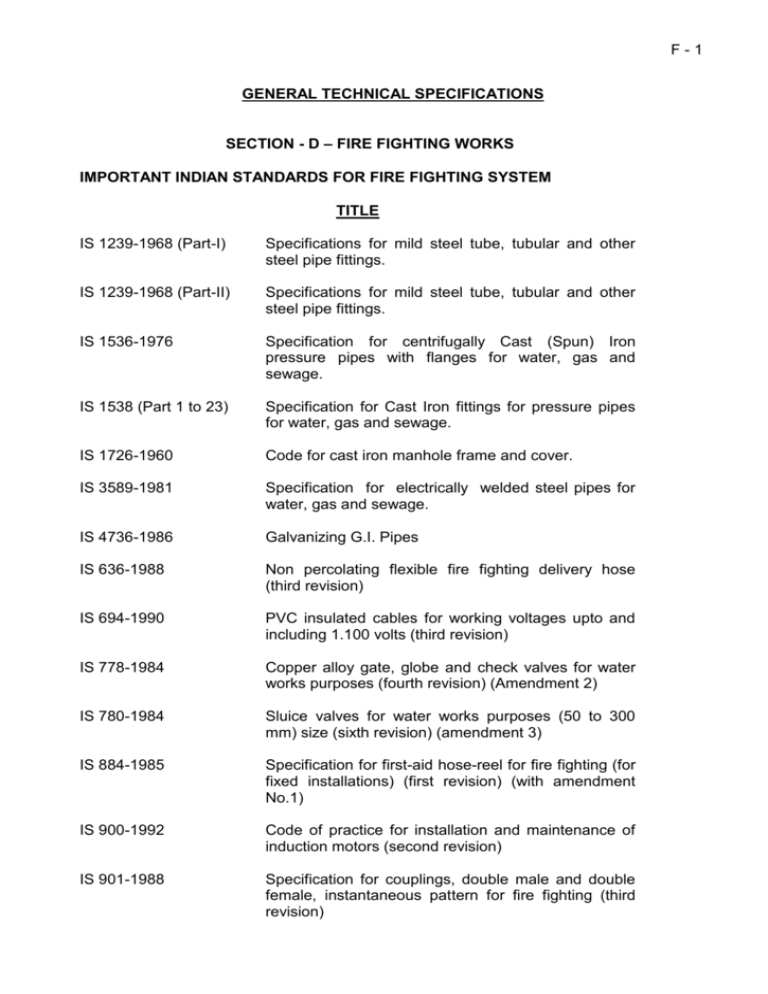
F-1 GENERAL TECHNICAL SPECIFICATIONS SECTION - D – FIRE FIGHTING WORKS IMPORTANT INDIAN STANDARDS FOR FIRE FIGHTING SYSTEM TITLE IS 1239-1968 (Part-I) Specifications for mild steel tube, tubular and other steel pipe fittings. IS 1239-1968 (Part-II) Specifications for mild steel tube, tubular and other steel pipe fittings. IS 1536-1976 Specification for centrifugally Cast (Spun) Iron pressure pipes with flanges for water, gas and sewage. IS 1538 (Part 1 to 23) Specification for Cast Iron fittings for pressure pipes for water, gas and sewage. IS 1726-1960 Code for cast iron manhole frame and cover. IS 3589-1981 Specification for electrically welded steel pipes for water, gas and sewage. IS 4736-1986 Galvanizing G.I. Pipes IS 636-1988 Non percolating flexible fire fighting delivery hose (third revision) IS 694-1990 PVC insulated cables for working voltages upto and including 1.100 volts (third revision) IS 778-1984 Copper alloy gate, globe and check valves for water works purposes (fourth revision) (Amendment 2) IS 780-1984 Sluice valves for water works purposes (50 to 300 mm) size (sixth revision) (amendment 3) IS 884-1985 Specification for first-aid hose-reel for fire fighting (for fixed installations) (first revision) (with amendment No.1) IS 900-1992 Code of practice for installation and maintenance of induction motors (second revision) IS 901-1988 Specification for couplings, double male and double female, instantaneous pattern for fire fighting (third revision) F-2 IS 902-1992 Suction hose coupling for fire fighting of purposes (third revision) IS 903-1984 Specification of fire hose delivery couplings branch pipe, nozzles and nozzle spanner (third revision) (Amendment 5) IS 937-1981 Specification for washers for water fittings for fire fighting purposes (revised) (with amendment No, 1) IS 1520-1980 Horizontal centrifugal pumps for clear cold, fresh water (second revision) IS 1536-1976 Horizontally cast iron pressure pipes for water, gas & sewage (first revision) (with Amendments No. 1 to 4) IS 1554-1988 Part I PVC insulated (heavy duty) electric cables (working voltage upto and including 1100 volts (third revision) IS 1554-1988 Part II PVC insulated (heavy duty) electric cables (working voltage from 3.3 KV upto and including 11 KV (second revision) IS 1648-1961 Code of practice for fire safety of buildings (General) Fire fighting equipment and its maintenance (with amendment No.1) IS 3624-1987 Pressure and vacuum gauges (Second revision) IS 4736-1968 Hot-dip zinc coatings on steel tubes (with Amendment No.1) IS 5290-1983 Specification for landing valves (second revision) (with Amendments No.6) IS 5312- 1984 Part I Swing check type reflux (non return) valves Part Isingle door pattern (with amendments nos. 1 & 2) IS 5312- 1986 Part II Swing check type reflux (non return) valves Part IIMulti door pattern (with amendments nos. 1 & 2) IS 7285 Seamless cylinders for storage of gas at high pressure. GENERAL F-3 1.0 Scope These general specifications cover the details of equipment , inspection as may be necessary before dispatch, delivery at site, installation, testing and commissioning, and handing over in working condition of the Fire Fighting System. 1.1 Conformity with statutory Act, Rules, Regulations Standards and Safety Codes 1.1.1 The wet riser and sprinkler system equipment, materials, accessories and their installation shall conform to relevant Indian Standard amended upto date the National Building Code part IV Fire protection and in conformity with the local Fire Regulations and Rules there under where they are in force. Provisions in local bylaws if any, shall be complied with. 1.1.2 All electrical works in connection with installation of wet riser system shall be carried out in accordance with the provision of Indian Electricity Act, 1910 and the Indian Electricity Rules, 1910, the Indian Electricity Rules, 1956 amended upto date and to CPWD General specifications for Electrical works Part I (internal) 1994 (External) amended upto date. 1.2 Works to be Done by the Contractor In addition to supply, installation, testing and commissioning of all equipments and materials as per schedule of work, the following works shall be deemed to be included within the scope of work to be executed by the contractor, whether or not indicated in the schedule of work. (i) All minor building work, such as cutting and making good the damages and filling up the hole in flooring with cement concrete, after laying the wet riser pipes. (ii) Small wiring including inter-connection etc. necessary to comply with the regulations as well as proper and trouble free operation of the equipment inclusive of all accessories. (iii) Necessary testing equipment for commissioning. (iv) Approval from Local Fire Authorities as may be required as per local byelaws. The contractor shall be responsible to arrange an inspection visit of concerned fire officer before start of work and shall carry out any rectification / modification as may be suggested by the Fire Officer and obtain necessary fire clearance certificate. (vi) The installation shall be carried out strictly in accordance with the approved drawing. (vii) RCC foundation for all pumps sets. (viii) Vibration elimination arrangements (anti-vibration pads) for all pumps sets. F-4 1.3 (ix) Necessary supports and clamps for pipes for the fire fighting, in the buildings, pump room. (x) Supporting brackets/frame work for the fuel oil tank and the fuel tank of capacity as mentioned in the schedule of quantities. (xi) Provision of necessary brick or cement concrete intermediate supports, as required in approved manner in case of soils which are not strong enough to support the pipes, thereby likely to cause differential settlement. (xii) Necessary anchor blocks of ample dimensions in cement concrete at all bends, Tees connections, foot of the wet riser, and other places as required to stand the pressure thrust in pipes. (xiii) Necessary masonry work/steel work for supporting hose cabinets for external (yard) hydrants. (xiv) All the required control piping, drain piping from the pumps to the drain point in the pump room, overflow piping from priming tank to the sump. The piping work shall include all necessary fittings, valves and accessories for effective functional requirements. Inspection and testing of materials 1.3.1 Contractor shall be required, if requested, to produce manufacturers test certificate for the particular batch of materials supplied to him. The tests carried out shall be as per the relevant Indian Standards. 1.3.2 For examination and testing of materials and works at the site Contractor shall provide all testing and gauging equipment necessary but not limited to the following: a. Theodolite b. Dumpy level c. Steel tapes d. Weighing machines e. Plumb bobs, spirit levels, hammers f. Micrometers, Tachometers g. Thermometers, stoves h. Hydraulic test machine i. Smoke test machine 1.3.3 All such equipment shall be tested for calibration at any approved laboratory, if required by the Engineer-in-Charge. 1.3.4 All testing equipment shall be preferably located in special room meant for the purpose. F-5 1.3.5 Samples of all materials shall be got approved before placing order and the approved samples shall be deposited with the Architects/Employer. 1.4 Metric conversion 1.4.1 All dimensions and sizes of materials and equipment given in the tender document are commercial metric sizes. 1.4.2 Any weights or sizes given in the tender having changed due to metric conversion, the nearest equivalent sizes accepted by Indian Standards shall be acceptable without any additional cost. 1.5 Reference points 1.5.1 Contractor shall provide permanent benchmarks, flag tops and other reference points for the proper execution of work and these shall be preserved till the end of the work. 1.5.2 All such reference points shall be in relation to the levels and locations, given in the architectural and plumbing drawings. 1.6 Contractor's rates 1.6.1 Rates quoted in this tender shall be inclusive of cost of materials, labor, supervision, erection, tools, plant, scaffolding, service connections, transport to site, taxes, octroi and levies, breakage, wastage and all such expenses as may be necessary and required to completely do all the items of work and put them in a working condition exclusive of work contract tax. 1.6.2 Rates quoted are for all heights and depths and in all positions as may be required for this work. 1.6.3 All rates quoted must be for complete items inclusive of all such accessories, fixtures and fixing arrangements, nuts, bolts, hangers as are a standard part of the particular item except where specially mentioned otherwise. 1.6.4 All rates quoted are inclusive of cutting holes and chases in walls and floors and making good the same with cement mortar/concrete of appropriate mix and strength as directed by Architects/Employer. Contractor shall provide holes, sleeves, and recesses in the concrete and masonry work as the work proceeds. 1.6.5 The Contractor shall furnish the EPI with vouchers, on request, to prove that the materials are as specified and to indicate that the rates at which the materials are purchased in order to work out the rate analysis of non tendered items which he may be called upon to carry out. 1.7 Site clearance and cleanup 1.7.1 The Contractor shall, from time to time, clear away all debris and excess materials accumulate at the site. 1.7.2 After the fixtures, equipment and appliances have been installed and commissioned, Contractor shall clean-up the same and remove all plaster, paints, stains, stickers and other foreign matter or discoloration leaving the same in a ready to use condition. 1.7.3 On completion of all works, Contractor shall demolish all stores, remove all surplus materials and leave the site in a broom clean condition, failing which the same shall be done at Contractor's risk and cost. F-6 1.8 Cutting of structural members 1.8.1 No structural member shall be chased or cut without the written permission of EPI. 1.9 Inspection of site and collection of data The tender shall be deemed to have examined the tender documents, detailed specification data etc. and to have visited the site or ascertained all relevant details for offering suitable equipment and for installation work. He shall be fully responsible for the system design. 1.10 Test Certificates Copies of all documents of routine test certificates of the equipment carried out at the manufacture’s premises shall be furnished to the EPI along with the supply of the equipment. 1.11 Care of buildings Care shall be taken, while handling/installing the equipment to avoid damage to the building. On completion of the installation, the contractor shall arrange to repair all damages to the building caused during installation so as to bring to the original condition. He shall also arrange to remove all unwanted waste materials from the buildings, pump room and other areas used by him. 1.12 Painting and Protection All equipment supplied shall be given final coat of paint over the primer after necessary treatment at the works before despatch. All damages to painting during transport and installation shall be set right or repainted to the satisfaction of the Employer/Architect before handing over. 1.13 Final Inspection and Testing When the installation is deemed by the contractor to be complete, he shall arrange with EPI for inspection and testing of the installation by the concerned local fire authorities. Test results obtained shall be recorded and installation shall not be accepted until the owner/inspecting officer is satisfied about its compliance with the requirement of these specifications. It shall be the responsibility of the contractor to carry out any rectification / modification as may be suggested by the Fire Officer and get the installation passed by the concerned local fire authorities, as may be required by the local by-laws, including payment of necessary Inspection fee or any other charges etc. 1.14 Guarantee The contractor shall guarantee the entire fire fighting installation as per specifications. All equipment shall be guaranteed for one year from the date of taking over against unsatisfactory performance or break down due to defective design, manufacture and installation. The installation shall be covered by the conditions that whole installation or any part thereof found defective within one F-7 year from the date of taking over shall be replaced or repaired by the contractor free of charge as decided by the department. The warranty shall cover the following: (a) Quality, strength and performance of materials use. (b) Safe mechanical and electrical stress on all parts under all specified conditions of operation. (c) Satisfactory operation during the maintenance period. 2.0 TESTING OF THE HYDRANT/SPRINKLER SYSTEM 2.1 Flushing of hydrant system: After installation of complete system flushing of hydrants system shall be done as under: a) Underground mains and lead-in connections to system risers shall be flushed before connections made to piping in order to remove foreign materials which may have entered underground during the course of installation. For hydrant system the flushing operation shall be continued until water is clear. b) Underground mains and connections shall be flushed at a flow rate of not less than 1620 ltrs. per minute. The pump and other equipment necessary for the flushing shall be arranged by the contractor at his own cost. c) The water coming out from the outlet will be connected to storm water drain by means of suitable hose. i) Starting up of the pressurization (Jockey) Pump The pressure switch shall be set at 6.5 kg /cm 2 at the lower limit and 7.0 kg/cm² at the upper limit. The system drain shall be opened to cause a drop in the pressure. The Jockey Pump shall start as soon as the pressure gauge needle falls down to 6.5 kg/cm². The Jockey Pump shall also automatically stop when the system has been pressurized again upto 7.0 kg /cm2. ii) The main electric pump shall be set to start at 5.5 kg/cm ². An external hydrant valve using a single length of hose and branch pipe shall be fully opened to cause a drop of pressure in the system. At first, the jockey pump shall start when the pressure drops to 6.5 kg/cm ². Further, drop in the pressure upto 5.5 kg/cm ² should be allowed to test automatic start-up of the main electrical fire pump. The Jockey Pump shall automatically stop at this stage. The external hydrant valve will be closed and the electrical pump shall continue to run and register rise in the pressure upto 7.0 kg/cm². The electrical pump shall be stopped manually by pressing the stop button. F-8 2.2 iii) After having the system got fully charged at 7.0 kg /cm² and the main electrical fire pump having stopped, the external hydrant valve using hose and branch pipe shall be opened again. After the sequence of automatic starting of the jockey pump at 6.5 kg/cm ² and starting of the main electrical fire pump at 5.5 kg/cm ² (the jockey pump will stop automatically at the starting of the main electrical fire pump), the power supply in the pump house shall be switched off. The standby pump shall automatically come into operation at a drop in pressure to 4 kg/cm². The standby pump will be allowed to run for 10 minutes. The external hydrant valve will be closed and standby pump will continue to run and register a rise in pressure upto 7.0 kg/cm². The standby pump will be stopped manually by pressing the stop button. iv) All these tests mentioned above shall be repeated after one hour interval. The result of all the tests shall be identical again. After the system has satisfactorily withstood the above tests, it can be taken over. Testing of the Piping 2.2.1 After laying and jointing the entire piping shall be tested to hydrostatic test pressure. The pipes shall be slowly charged with water so that the air is expelled from the pipes. The pipes shall be allowed to stand full of water for a period of not less than 24 hours and then tested under pressure. The test pressure shall be at least 1.5 times the operating pressure. The test pressure shall be applied by means of an electrical test pump to be provided by the contractor. Precautions shall be taken to ensure that the required test pressure is not exceeded. 2.2.2 The open end of the piping shall be temporarily closed for testing. 2.2.3 All leaks and defects in the pipes, joints, valves etc. noticed during the testing and before commissioning shall be rectified to the satisfaction of Engineer-in-charge. F-9 ELECTRIC FIRE PUMPS 3.0 Scope This section covers the details of requirements of the electrical fire pumps. 3.1 Electric Pumps The electric fire pump shall be suitable for automatic operation complete with necessary electric motor and automatic starting gear. Electric motor shall be suitable for 415V + 10%, 3 phase, 50Hz, A.C. supply. The class of insulation shall be B. 3.1.1 Main/Sprinkler/Terrace Electrical Fire Pump The main electrical fire pump should be capable of delivering 150% of its rated discharge at least 65% of its rated head. Motor starter shall be automatic star delta type . The unit shall include suitable CT and ammeter on one line and shall not incorporate under voltage / no voltage trip, overload or SPP. The starter assembly shall be integrated in the power and control panel of the system. 3.1.2 Pressurization (Jockey) Pump The discharge of the pressurization pump shall be as per the schedule of quantities. F - 10 PIPING FOR WET RISER/SPRINKLER SYSTEM 4.0 Scope This section covers the details of requirement of piping used in wet riser system, including the associated auxiliary equipment. 4.1 4.2 Pipes and Pipe Work a) All materials shall be of the best quality conforming to the specifications and subject to the approval of the Engineer-in-charge. b) Pipes shall be securely fixed to walls, and the ceiling by suitable suspenders and clamps at intervals not exceeding 1.5 meter. c) Valves and other accessories shall be so located that they are easily accessible for operations, repairs and maintenance. d) The piping system shall be capable of withstanding 150% of the working pressure including water hammer effects. e) For MS pipelines upto 50 mm dia screwed jointing shall be adopted, while for pipelines above 50 mm dia welded flanged construction is to be carried out. f) Flanged joints shall be used for connections to vessels, equipment, flanged valves etc. respective of the pipe size. g) Pipes shall be buried at-least one meter below ground level and shall have 230 mm x 230 mm masonry supports at-least 300 mm high at 3 m intervals. Masonry work to have plain cement concrete foundation (1 cement : 4 coarse sand : 8 stone aggregate ) of size 380 x 380 x 75 thick resting on firm soil. h) Sluice valve shall be kept in open position and the scope of work includes provision of necessary leather strap and pad lock so as to prevent unauthorized closing of valve. i) The installation work include provision of all clamps, supports anchors etc. which will be as per drawing. PROTECTION a) All pipes above ground and in exposed locations shall be painted with one coat of Red Oxide primer and two or more coats or synthetic enamel paint of approved shade. b) All MS pipes under floors or below ground shall be provided with protection against soil corrosion by applying two coats of coal tar hot enamel paint, polythene tape and finished with one coat of the above paint (80/95 grade bitumen). F - 11 c) All M.S. pipes below ground shall be laid on a layer of 7.5 cm coarse sand (Zone IV) and filled upto 15 cm above the pipes. 4.3 Air Vessel and Air Release Valve Air vessel on top of each wet riser piping shall be fabricated of at least 10 mm thick GI sheet to withstand the pressure, i.c (dished ends and supporting legs). This shall be of 450mm dia. and 2.0 m high. This shall be complete with necessary flange connection to the wet riser piping and air release valve with necessary piping to meet the functional requirement of the system. The air vessel shall be continuous welded construction. This shall be tested for twice the working pressure at the works and necessary test certificates shall be furnished. 4.4 Valves, gauges and orifice plates 4.4.1 Sluice valve above 65mm shall be of cast iron body and bronze/gunmetal seat. They shall conform to type PN 1.6 of I.S. : 780-1980, valves upto 65mm shall be of brass construction. Valve wheels shall be of right hand type and have arrow head engraved or cast thereon showing the direction for turning open and closing. 4.4.2 Non return valve shall be of cast iron body and bronze gunmetal seat. They shall conform to class I of IS: 5312 and have flanged ends. They shall be swing check type in horizontal runs and lift check type in the vertical runs of piping. They shall not be spring loaded type. 4.4.3 Pressure gauge of suitable range shall be installed on the discharge side of each pump. Vacuum gauge shall be provided on suction side for pumps with negative suction. The dial size shall be 150mm. The gauge shall be with necessary cocks. 4.4.4 Orifice plates shall be of 6mm thick stainless steel to reduce pressure on individual hydrants to operating pressure of 3.5 kg/sq.cm. Design of the same shall be given by the contractor as per location and pressure condition of each hydrant. 4.5 External Yard Hydrants 4.5.1 External Yard Hydrants shall be of ‘Stand Post’ type conforming to IS-:908-1975 and comprise of stand post for single outlet, duck foot bend, flanged riser and single headed brass/gunmetal valve conforming to type A of IS. 5290-1977. 4.5.2 The stand post column shall be cast iron, cast in one piece, conforming to Grade 20 of IS:210-1970. The internal diameter at the top shall be at least 80mm. 4.5.3 External (yard) hydrants shall be located to have the outlet at about 1m above ground level. 4.5.4 Where external hydrants below ground level are specifically indicated in tender specifications, there shall be enclosed in masonry or casr iron structure of size 75 cm square and 8cm above ground level. The hydrant shall be within 8 cm from the top of the enclosure. F - 12 4.5.5 The outlet of yard hydrants shall be angled to the ground with an instantaneous spring lock type gunmetal female coupling of 63mm dia for connecting to the hose pipe. 4.6 Internal Hydrants 4.6.1 The internal hydrant outlet shall comprise single headed single outlet gunmetal landing valve conforming to type ‘A’ of I.S. 5290-1977. On the head shall form part of the landing valve construction. 4.6.2 Internal hydrants at each floor shall be located at about 1m above floor level. 4.7 First Aid Hose Reel equipment 4.7.1 First Aid hose reel equipment shall comprise reel, hose guide fixing bracket, hose tubing, globe valve, stop cock and nozzle . This shall conform to IS-884-1969. The hose tubing shall conform to IS:1532-1969. 4.7.2 The hose tubing shall be 20mm dia and 30m long. The nozzle and globe valve shall be of 20mm size. 4.7.3 The fixing bracket shall be of swinging type. Operating instructions shall be engraved on the assembly. 4.8 Hose Pipes 4.8.1 Hose pipe shall be of non-percolating type as per IS 636-1979 (Type B).With nominal size of 63mm and lengths of 15m , as per quantities specified for each. 4.8.2 All hose pipes shall carry ISI marking on the body of the hose. 4.8.3 The hose shall have instantaneous spring lock-type coupling on ends. The instantaneous coupling shall be as per IS : 903. It shall be fixed to each other by copper rivets and galvanized M.S. wires and leather bands. All coupling shall be interchangeable with each other, and shall bear ISI markings. 4.9 HOSE REEL The hose reel shall be directly tapped from the riser through a 25 mm dia pipe, the drum and reel being firmly held against the wall by use of dash fasteners. The hose reel shall be swinging type (180° ) and the entire drum, reel etc. shall be as per IS : 3876 and IS : 884. The rubber tubing shall be of best quality and the Gun Metal nozzle shall be 16 mm dia shut off type as per IS 8090-1976 selected out of list of approved makes. 4.10 BRANCH PIPES Branch pipe shall be of either gunmetal or Aluminium and should conform to IS:903. One end of the branch pipe will receive the coupling while the other end shall have a nozzle screwed to it. It shall bear ISI marking. F - 13 4.11 HOSE CABINETS Each hydrant shall be housed in a Hose cabinet of suitable size. The Hydrant Cabinet shall hold single headed hydrant 2 hoses and one branch pipe as required. Internal hydrants shall normally fit the niche made for it. The cabinet shall be of minimum 1.6mm sheet, glazed doors (clear glass of 4 mm thickness) . The glass shall be firmly fixed by means of steel clips and screws with rubber beading. Hinges shall also be screwed and not welded. The steel work shall have one coat of primer and two coats of red enamel paint. The words "Yard Hydrant" , "Hydrant' etc., should be painted in white or red on the glass in 75 mm high letters, The Hose Box shall be lockable. 4.12 FIRE BRIGADE INLET CONNECTION A two way fire brigade inlet connection with a non-return valve as per IS 904-1983 shall be provided to facilitate the fire brigade to pump water into the system by the use of their own equipment. This shall be housed in a M.S. cabinet with glass fronted door as per drawing. 4.13 FIRE BRIGADE INLET AND DRAW OFF CONNECTION a. Inlet connection – a four way gun metal inlet connection as per IS 904-1983 shall be provided at the Fire Storage Tank for filling of the tank by the fire Brigade, through a 150mm dia. inlet Pipe. The connection will have the option to pressurize the building Fire System (by the Fire Brigade directly) by provision of sluice valves, tee and bend as per drawings. b. Draw off connection – a draw off connection for drawing the water from the Fire Tank would be provided next to the inlet connection to enable Fire Brigade to draw water from the Fire Tank. This shall consist of a gun metal stand draw off connection with a gunmetal blank cap and a chain. A 150mm suction pipe with a foot valve and strainer shall be provided as per drawings. c. M.S. cabinet, for enclosing both inlet and outlet connection shall be provided as per drawings. F - 14 LIST OF APPROVED MAKES FOR FIRE FIGHTING & FIRE DETECTION SYSTEM 01 02 PUMPS MOTORS Kirloskar /Mather & Platt GE /Siemens/Crompton Greaves/KEC 03 MOTOR CONTROL SWITCHES /STARTERS L&T/ Siemens /ABB/GE 04 PRESSURE SWITCH 05 06 PRESSURE GAUGE CABLES, WIRES 07 08 11 GI/MS PIPES CAST IRON SLUICE & NON RETURN VALVES GUNMENTAL BALL, NON RETURN VALVES HYDRANT VALVE, BRANCH PIPES,HOSE REELS/NOZZLES HOSE PIPES INDFOSS / SWITZER/Mobrey/System Sensor FIEBIG / H GURU / PRICOL NATIONAL/HAVELLS/RALISON/Ecko/ Skytone Tata Steel, Jindal, Hissar, Kalinga Sant/Leader/Kirloskar/Kalpana/Arrow/C&R/ Castle RB/Zolotto/Cim 12 HOSE BOXES LOCALLY FABRICATED 13 FIRE BRIGADE INLET D.S.S. / SUPER / Newage / Minimax 14 SPRINKLERS, ALARM VALVE H.D. / ACE / SPRAYSAFE / CENTRAL/DSS 15 16 VIJAY/MINIMAX/Safeway/Agni SANT/Leader /Kirloskar/C&R 17 18 FIRE ALARM PANEL SUCTION STRINERS WITH FOOT VALVE HOSE REEL FIRE EXTINGUISHERS 19 INDICATING LAMPS Siemens/L&T/GE Power Controls/Vaisno 20 APPOLLO / AGNI / TAC APPROVED 21 HOOTER/Manual Call Point/Talk Balk Unit Conduits 22 BATTERY Exide 23 ELECTRICAL CONTROL PANEL AMPTECH INDIA (P) LTD./ KRYPTON ENGG. CO./ MILESTONE SWITCHGEAR (P) LTD./ KANISHKA POWER CONTROLS P. LTD./ PIECO INDIA ELECTRIC Co. 24 FIRE RESISTANT PAINT Viper 09 10 MINIMAX/NEWAGE/VIJAY/SUPER NEWAGE / JAY SHREE/VIJAY ISI Marked Newage/Minimax/Vijay BEC/Steelkraft Note : The contractor shall get the samples of all the items covered and not covered in his list approved from EPI before commencing the supply.
