Section #23 34 00
advertisement
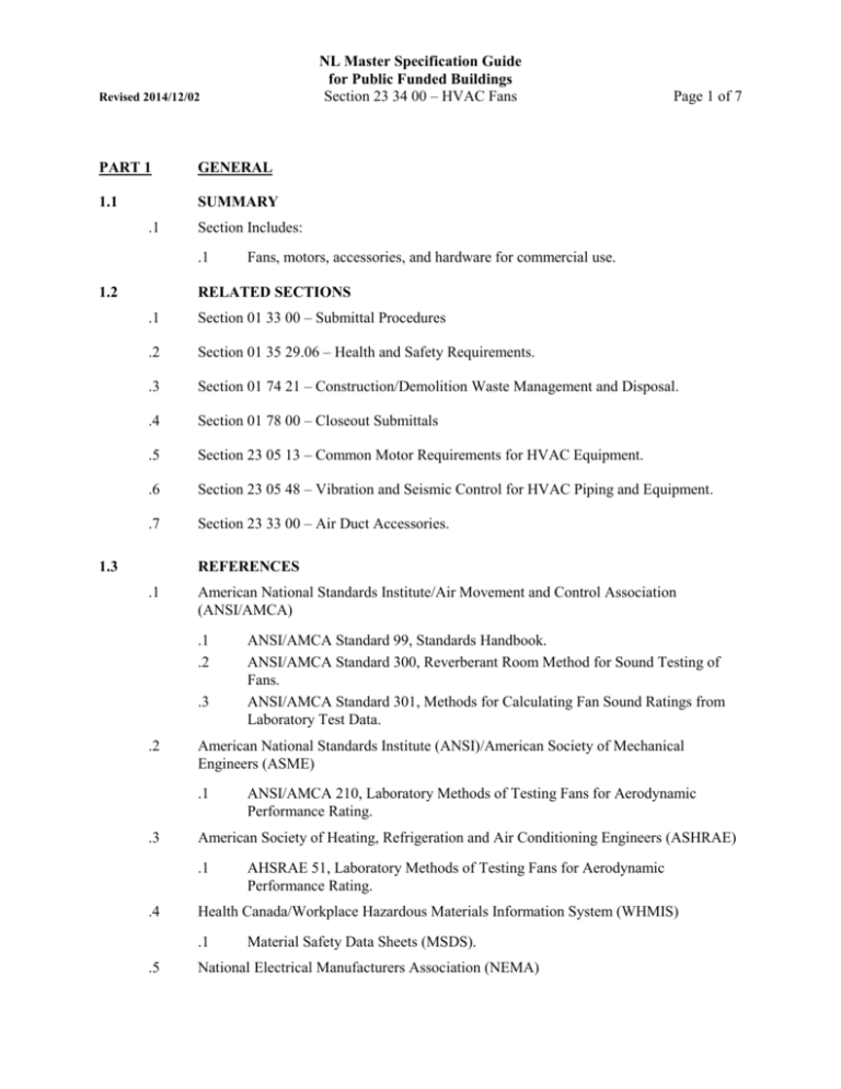
NL Master Specification Guide for Public Funded Buildings Section 23 34 00 – HVAC Fans Revised 2014/12/02 PART 1 GENERAL 1.1 SUMMARY .1 Section Includes: .1 1.2 Page 1 of 7 Fans, motors, accessories, and hardware for commercial use. RELATED SECTIONS .1 Section 01 33 00 – Submittal Procedures .2 Section 01 35 29.06 – Health and Safety Requirements. .3 Section 01 74 21 – Construction/Demolition Waste Management and Disposal. .4 Section 01 78 00 – Closeout Submittals .5 Section 23 05 13 – Common Motor Requirements for HVAC Equipment. .6 Section 23 05 48 – Vibration and Seismic Control for HVAC Piping and Equipment. .7 Section 23 33 00 – Air Duct Accessories. 1.3 REFERENCES .1 American National Standards Institute/Air Movement and Control Association (ANSI/AMCA) .1 .2 .3 .2 American National Standards Institute (ANSI)/American Society of Mechanical Engineers (ASME) .1 .3 AHSRAE 51, Laboratory Methods of Testing Fans for Aerodynamic Performance Rating. Health Canada/Workplace Hazardous Materials Information System (WHMIS) .1 .5 ANSI/AMCA 210, Laboratory Methods of Testing Fans for Aerodynamic Performance Rating. American Society of Heating, Refrigeration and Air Conditioning Engineers (ASHRAE) .1 .4 ANSI/AMCA Standard 99, Standards Handbook. ANSI/AMCA Standard 300, Reverberant Room Method for Sound Testing of Fans. ANSI/AMCA Standard 301, Methods for Calculating Fan Sound Ratings from Laboratory Test Data. Material Safety Data Sheets (MSDS). National Electrical Manufacturers Association (NEMA) NL Master Specification Guide for Public Funded Buildings Section 23 34 00 – HVAC Fans Revised 2014/12/02 .1 .2 .6 NEMA MG 1 Motors and Generators NEMA ICS 7.1 Safety Standard for Construction and Guide for Selection, Installation and Operation of Adjustable Drive Systems. The Master Painters Institute (MPI) .1 1.4 Page 2 of 7 Architectural Painting Specification Manual, MPI #18, Primer, Zinc Rich, Organic. SYSTEM DESCRIPTION .1 Performance Requirements: .1 .2 .3 .4 .5 1.5 Catalogued or published ratings for manufactured items: obtained from tests carried out by manufacturer or those ordered by manufacturer from independent testing agency signifying adherence to codes and standards in force. Capacity: flow rate, total static pressure, bhp W, efficiency, revolutions per minute, power, model, size, sound power data and as indicated on schedule. Fans: statically and dynamically balanced, constructed in conformity with AMCA 99. Sound ratings: comply with AMCA 301, tested to AMCA 300. Supply unit with AMCA certified sound rating seal. Performance ratings: based on tests performed in accordance with ANSI/AMCA 210. Supply unit with AMCA certified rating seal, except for propeller fans smaller than 300 mm diameter. SUBMITTALS .1 Product Data: .1 .2 Shop Drawings: .1 .3 Submit shop drawings and product data in accordance with Section 01 33 00 Submittal Procedures. Provide: .1 .2 .3 .4 .4 Submit manufacturer's printed product literature, specifications and datasheet in accordance with Section 01 33 00 - Submittal Procedures. Include product characteristics, performance criteria, and limitations. .1 Submit two copies of Workplace Hazardous Materials Information System (WHMIS) Material Safety Data Sheets (MSDS) in accordance with Section 01 33 00 - Submittal Procedures. Fan performance curves showing point of operation, BHP kW and efficiency. Sound rating data at point of operation. Dimensional data. Installation procedures. Indicate: NL Master Specification Guide for Public Funded Buildings Section 23 34 00 – HVAC Fans Revised 2014/12/02 .1 .2 .5 .2 Certificates: submit certificates signed by manufacturer certifying that materials comply with specified performance characteristics and physical properties. Instructions: submit manufacturer's installation instructions. Closeout Submittals: .1 1.6 Motors, sheaves, bearings, shaft details Minimum performance achievable with variable speed controllers and variable inlet vanes as appropriate. Quality assurance submittals: submit following in accordance with Section 01 33 00 Submittal Procedures. .1 .6 Page 3 of 7 Provide operation and maintenance data for incorporation into manual specified in Section 01 78 00 - Closeout Submittals. QUALITY ASSURANCE .1 1.7 Health and Safety Requirements: do construction occupational health and safety in accordance with Section 01 35 29.06 - Health and Safety Requirements. MAINTENANCE .1 Extra Materials: .1 .2 1.8 Provide maintenance materials in accordance with Section 01 78 00 - Closeout Submittals. .1 Spare parts to include: .1 Matched sets of belts. Furnish list of individual manufacturer's recommended spare parts for equipment, include: .1 Bearings and seals. .2 Belts .3 Addresses of suppliers. .4 List of specialized tools necessary for adjusting, repairing or replacing. DELIVERY, STORAGE, AND HANDLING .1 Packing, shipping, handling and unloading: .1 .2 .2 Deliver, store and handle in accordance with Section 01 61 00 - Common Product Requirements. Deliver, store and handle materials in accordance with manufacturer's written instructions. Waste Management and Disposal: .1 Construction/Demolition Waste Management and Disposal: separate waste materials for reuse and recycling in accordance with Section 01 74 21 Construction/Demolition Waste Management and Disposal. NL Master Specification Guide for Public Funded Buildings Section 23 34 00 – HVAC Fans Revised 2014/12/02 PART 2 PRODUCTS 2.1 FANS GENERAL Page 4 of 7 .1 Capacity: flow rate, static pressure, bhp, efficiency, revolutions per minute, power, model, size, sound power data and as indicated on schedule. .2 Fans: statically and dynamically balanced, constructed in conformity with AMCA 99. .3 Sound ratings: comply with AMCA 301, tested to AMCA 300. Unit shall bear AMCA certified sound rating seal. .4 Performance ratings: based on tests performed in accordance with ANSI/AMCA 210, and ANSI/ASHRAE 51. Unit shall bear AMCA certified rating seal, except for propeller fans smaller than 300 mm diameter. .5 Motors: .1 .2 .3 .4 .5 .6 Open drip proof outside of air stream, TEFC when in air stream, explosion proof as indicated in accordance with NEMA MG1. In accordance with Section 23 05 13 – Common Motor Requirements for HVAC Equipment supplemented as specified herein. For use with variable speed controllers where specified. Sizes as specified. Two speed with two windings and speeds of approximately 1200 or 900 r/min low and 1800 r/min high as indicated. Two speeds with split winding, constant horsepower or constant or variable torque as specified and speeds as indicated. .6 Accessories and hardware: matched sets of V-belt drives, adjustable slide rail motor bases, belt guards, coupling guards, fan inlet and/or outlet safety screens as indicated and as specified in Section 23 05 13 – Common Motor Requirements for HVAC Equipment, inlet or outlet dampers and vanes and as indicated. .7 Factory primed before assembly in colour standard to manufacturer. .8 Scroll casing drains: as indicated. .9 Finish on fume hood exhaust fans: heresite coated .10 Bearing lubrication systems plus extension lubrication tubes where bearings are not easily accessible. .11 Vibration isolation: to Section 23 05 48 - Vibration and Seismic Control for HVAC Piping and Equipment. .12 Flexible connections: to Section 23 33 00 – Air Duct Accessories. NL Master Specification Guide for Public Funded Buildings Section 23 34 00 – HVAC Fans Revised 2014/12/02 2.2 Page 5 of 7 CENTRIFUGAL FANS .1 Fan wheels: .1 .2 .3 .2 Bearings: air handling quality, heavy duty, split pillow-block, flange mounted grease lubricated ball or roller self aligning type with oil retaining, dust excluding seals and a certified minimum rated life to ABMA L10 of 100,000 hours. Shaft seals on laboratory fume hood and biological safety cabinet exhaust fans: .1 .3 .2 .3 .4 Volute with inlet cones: fabricated steel for wheels 300 mm or greater, cast iron, or steel, for smaller wheels, braced, and with welded supports. For horizontally and vertically split housings provide flanges on each section for bolting together, with gaskets of non-oxidizing non-flammable material. Provide bolted latched airtight access doors with handles. Spark resistant construction Type B minimum where indicated. Variable volume control devices: .1 .2 .3 2.3 Single disc or stuffing box seals. Housings: .1 .4 Welded steel or aluminum construction. Maximum operating speed of centrifugal fans not more than 40 % of first critical speed. Air foil or backward inclined blades, as indicated. Mounted by fan manufacturer. Adjustable inlet vanes: operated from a centre mechanism linked to each damper vane. Support each vane at ends in bronze bearings. On DWDI fans interconnect vanes to operate in unison. Provide locking devices for manual operation. Variable Speed Drives: to NEMA ICS 7.1. CABINET FANS - GENERAL PURPOSE .1 Fan characteristics and construction: as centrifugal fans. .2 Cabinet hung single or multiple wheels with DWDI centrifugal fans in factory fabricated casing complete with vibration isolators and seismic control measures, motor, direct drive or V-belt drive and guard outside casing. .3 Fabricate casing of zinc coated or phosphate treated steel reinforced and braced for rigidity. Provide removable panels for access to interior. Uncoated, steel parts shall be painted over with corrosion resistant paint to MPI #18. Finish inside and out, over prime coat, with rust resistant enamel to Section 09 91 13 – Exterior Painting. Internally line cabinet with 12-25 mm thick rigid acoustic insulation, pinned and cemented, complete with metal nosings on all exposed edges. 2.4 UTILITY SETS .1 Characteristics and construction: for centrifugal fans. NL Master Specification Guide for Public Funded Buildings Section 23 34 00 – HVAC Fans Revised 2014/12/02 Page 6 of 7 .2 Preassemble single width centrifugal fan with removable protective hood with vents, and automatic spring loaded back draft dampers and 12 mm mesh birdscreens where indicated. .3 Provide belt driven sets with adjustable motor bed plate and variable pitch driver sheave. 2.5 AXIAL FLOW FANS (TUBE-AXIAL OR VANE-AXIAL) .1 Casings: welded steel with welded motor support, hinged or bolted access plates, streamlined inlet cone and discharge bell sections. .2 Blade material: steel or aluminum. Hub material: steel or aluminum. .3 Supports: .1 .2 Floor mounted units: reinforced legs. Ceiling suspended units: support brackets welded to side of casing. Extend grease lubrication facilities to outside of casing. .4 Bearings: ball or roller with extension tubes to outside of casing. .5 Direct drive: .1 .2 .3 .4 .6 Belt drive: .1 .2 .3 2.6 Adjustable or fixed blade wheels as indicated: totally-enclosed, air over motors. Diameter of wheel hub: at least equal to that of motor frame. Adjustable blades for varying range of volume and pressure. Provide permanent pitch angle indication vernier scale on hub. Provide for automatic adjustment while in motion. Provide adjustment stops to avoid overloading motor. Variable speed drives: to NEMA ICS 7.1. Fixed or adjustable blade as indicated by externally mounted motors through Vbelt drive. Provide internal belt fairing, external belt guards and adjustable motor mounts. Adjust blades for varying range of volume and pressure. Hubs shall facilitate indexing of blade angle. Provide automatic adjustment stops to avoid overloading motor. Variable speed drives: to NEMA ICS 7.1. IN-LINE CENTRIFUGAL FANS .1 Characteristics and construction: as for centrifugal fan wheels, with axial flow construction and direct or belt drive as indicated. .2 Provide AMCA arrangements 1 or 9 as indicated with stiffened flanges, smooth rounded inlets, and stationary guide vanes. .3 Acceptable Product: Trane, Sheldons, Barry Blower, Cook, Penn, Woods, Greenheck. Revised 2014/12/02 2.7 NL Master Specification Guide for Public Funded Buildings Section 23 34 00 – HVAC Fans Page 7 of 7 PROPELLER FANS .1 Fabricate multibladed propellers of sheet steel or aluminum of airfoil shape within bell mouth entrance on integral mounts, with grease lubricated ball bearings, with extended lubrication fittings, suited for operating in any position, direct or belt driven, complete with motor as indicated. .2 Provide blade guards, bird screen and automatic back draft dampers on discharge, with gasketted edges. .3 Acceptable Product: Penn, Cook, Woods, Greenheck, ACME, Carnes. PART 3 EXECUTION 3.1 MANUFACTURER’S INSTRUCTIONS .1 3.2 Compliance: comply with manufacturer's written recommendations or specifications, including product technical bulletins, handling, storage and installation instructions, and datasheet. FAN INSTALLATION .1 Install fans as indicated, complete with resilient mountings specified in Section 23 05 48 - Vibration and Seismic Control for HVAC and Piping Equipment, flexible electrical leads and flexible connections in accordance with Section 23 33 00 – Air Duct Accessories. .2 Provide sheaves and belts required for final air balance. .3 Bearings and extension tubes to be easily accessible. .4 Access doors and access panels to be easily accessible. 3.3 CLEANING .1 Proceed in accordance with Section 01 74 11 - Cleaning. .2 Upon completion and verification of performance of installation, remove surplus materials, excess materials, rubbish, tools and equipment. 3.4 COMMISSIONING .1 Commissioning in accordance with Section 01 91 13 – General Commissioning (Cx) Requirements. END OF SECTION
