fulltext - International Association for Automation and
advertisement
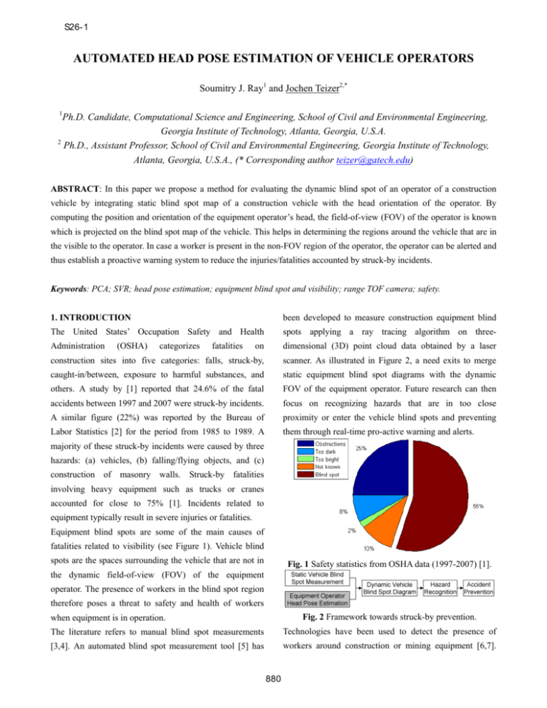
S26-1 AUTOMATED HEAD POSE ESTIMATION OF VEHICLE OPERATORS Soumitry J. Ray1 and Jochen Teizer2,* 1 Ph.D. Candidate, Computational Science and Engineering, School of Civil and Environmental Engineering, Georgia Institute of Technology, Atlanta, Georgia, U.S.A. 2 Ph.D., Assistant Professor, School of Civil and Environmental Engineering, Georgia Institute of Technology, Atlanta, Georgia, U.S.A., (* Corresponding author teizer@gatech.edu) ABSTRACT: In this paper we propose a method for evaluating the dynamic blind spot of an operator of a construction vehicle by integrating static blind spot map of a construction vehicle with the head orientation of the operator. By computing the position and orientation of the equipment operator’s head, the field-of-view (FOV) of the operator is known which is projected on the blind spot map of the vehicle. This helps in determining the regions around the vehicle that are in the visible to the operator. In case a worker is present in the non-FOV region of the operator, the operator can be alerted and thus establish a proactive warning system to reduce the injuries/fatalities accounted by struck-by incidents. Keywords: PCA; SVR; head pose estimation; equipment blind spot and visibility; range TOF camera; safety. 1. INTRODUCTION been developed to measure construction equipment blind The United States’ Occupation Safety and Health spots applying a ray tracing algorithm on three- Administration on dimensional (3D) point cloud data obtained by a laser construction sites into five categories: falls, struck-by, scanner. As illustrated in Figure 2, a need exits to merge caught-in/between, exposure to harmful substances, and static equipment blind spot diagrams with the dynamic others. A study by [1] reported that 24.6% of the fatal FOV of the equipment operator. Future research can then accidents between 1997 and 2007 were struck-by incidents. focus on recognizing hazards that are in too close A similar figure (22%) was reported by the Bureau of proximity or enter the vehicle blind spots and preventing Labor Statistics [2] for the period from 1985 to 1989. A them through real-time pro-active warning and alerts. (OSHA) categorizes fatalities majority of these struck-by incidents were caused by three hazards: (a) vehicles, (b) falling/flying objects, and (c) construction of masonry walls. Struck-by fatalities involving heavy equipment such as trucks or cranes accounted for close to 75% [1]. Incidents related to equipment typically result in severe injuries or fatalities. Equipment blind spots are some of the main causes of fatalities related to visibility (see Figure 1). Vehicle blind spots are the spaces surrounding the vehicle that are not in Fig. 1 Safety statistics from OSHA data (1997-2007) [1]. the dynamic field-of-view (FOV) of the equipment operator. The presence of workers in the blind spot region therefore poses a threat to safety and health of workers Fig. 2 Framework towards struck-by prevention. when equipment is in operation. The literature refers to manual blind spot measurements Technologies have been used to detect the presence of [3,4]. An automated blind spot measurement tool [5] has workers around construction or mining equipment [6,7]. 880 S26-1 One of the approaches [7] uses radio frequency (RF) [8,9,10]. Most of the existing head pose estimation warning technology to scan for workers in the proximity of techniques either make use of intensity images or spatial construction vehicles. When workers equipped with the (3D) data. A recent study [12] classified these techniques RFID warning are within a predefined proximity distance into eight categories. Based upon the approach used to to the equipment mounted RFID antenna, the worker and solve the head pose estimation problem, the methods have operator receive alerts. The alert types are audio, visual, or been broadly classified into: (a) appearance based methods, vibration, depending on the work task or equipment type. (b) detector array methods, (c) non-linear regression As such real-time pro-active technology has the potential models, (d) manifold embedding methods, (e) flexible to save life(s) by pro-actively monitoring the surroundings models, (f) geometric methods, (g) tracking methods, and of a piece of equipment, the inherent limitation of such (h) hybrid methods. Some of their strengths and gaps of systems is it only takes into account the proximity of the relevant techniques are presented in abbreviated form. workers to the equipment and does not incorporate any Few have addressed the issue to utilize range imaging knowledge of the operator’s FOV. Hence, false-negative cameras which are also widely known as three-dimensional alerts (when the operator has visual contact to workers) are (3D) cameras or Flash Laser Detection and Ranging (Flash preventable. To address this issue, knowing the operator’s LADAR) [11]. Unlike intensity cameras, range imaging FOV may help in understanding better when warnings and cameras capture spatial information of the viewed scene alerts should be activated. without depending on ambient illumination. This paper presents a novel method that computes the 3. METHODOLOGY coarse head orientation and pose of a construction In this study, coarse head pose angles are estimated by equipment operator using emerging range imaging fitting a 3D line to the nose ridge and calculating a technology. The paper is organized as follows: first we symmetry plane. The proposed approach assumes that the discuss existing literature in head pose estimation, nose tip is the closest point to the camera at the start of followed by the research methodology. Details to the gathering range frames. Similar to many of the other vision developed coarse head pose and orientation model training based head pose estimation algorithms that utilize only one and computation algorithms are next. We then present camera, the proposed approach may not be suitable for results to the performance of the developed model under applications where the head undergoes very large rotations, different experimental settings in laboratory and live e.g. yaw angles close to +⁄- 90° (0° meaning the person construction environments. As a note, we refer to the pose looks straight ahead). A further assumption is based on the estimation algorithm as a model. relatively low resolution commercially available range 2. BACKGROUND cameras provide. Range cameras [11] have relatively low Head orientation or pose estimation typically refers to the resolutions (176×144 pixels) and tend to be noisy with measurement of three angles of the human head: pitch, yaw, distance errors of single pixels close to four centimeters. and roll. Pitch refers to the angles formed by the head Since other methods such as the computation of surface during up-and-down motion (turn around the X-axis). Roll curvatures would be vulnerable to the noisy measurements refers to the angles formed by tilting the head towards of a range camera, we solve the head pose estimation along left and right direction (rotation around the Z-axis). problem by extracting the geometric head features using a Yaw refers to the angles formed by rotating the head range camera. We term these features as feature vectors. towards the left and right direction (rotation around the Y- The representation of a range image in form of feature axis). Therefore, the orientation of an object can be vectors is achieved by performing the PCA of the range determined by estimating these three angles. image. This step helps us to scale down the range image Multiple studies have solved the pose estimation problem from 176×144×3 dimensions to a 1×18 vector. This to determine driver attention using stereo or vision cameras reduction in dimensions reduces the computational burden 881 S26-1 in the prediction stage. These feature vectors corresponding (2) Viewpoint Transformation: The orientation of the head to different view poses are then trained on a support vector was measured with respect to the camera coordinate regression model. system. The coordinate axes of the camera coordinate The range image data are captured using a single system was transformed to the cabin coordinate system. commercially-available range imaging cameras mounted at (3) Head Segmentation: The captured face appears in the cabin frame of the construction equipment (see Figure Figure 4 and a bounding box algorithm was used to extract 3). This Time-of-Flight (TOF) camera outputs spatial and the head region from the points that pass a distance intensity data to each pixel in the frame it captures at high threshold test. Figure 4 shows the extracted point cloud update rates (up to 50 Hz). data of the head. This segmentation yields a set of N points that represent the head. Let this set be denoted by Xim with dimensions N*D, where N is the number of points and D is the number of dimensions, i.e., D = 3. (4) Principal Component Analysis (PCA): PCA is a dimensional reduction technique that is applied to map the images from high dimensional space to the eigenspace. We use PCA to extract the coefficient of the principal components. We then map the coefficient in form of vectors on to the image data space. The three feature vectors in the image data space are shown in Figure 5. The original image of size 144×176×3 has been reduced to a Fig. 3 Range camera setting and angle definition. Amplitude values and a 3D median filter help to partially 1×18 vector (saving the computational effort). remove noisy pixels. Each of the range images is then (5) Support Vector Regression: Support vector machine processed to automatically segment the point cloud data of approaches [13, 14] were used as a very powerful the operator head by defining a bounding box. To extract classification features that incorporate the geometric information of the performances. head pose a PCA is run on the extracted point cloud data of orientation were the next steps. and regression Estimation and methods with validation robust of head the head. These extracted geometric features are then used along with ground truth data to train the SVR model. We propose two different SVR models for estimating the yaw and pitch angles. The detailed method of collecting ground truth data is explained in one of the following sections. To predict the head orientation in a new range image, first Fig. 4 Raw 3D point cloud data and extracted head after the head is extracted from the spatial point cloud data and applying threshold and filter. then the head’s geometric features are computed using the PCA. The extracted features are then used as input to the SVR model to predict the head orientation. The following steps explain the developed algorithm: (1) Noise removal: Spatial data from range imaging cameras inherently contains noise (errors). Our approach was to remove noisy pixels thorugh online 3D median filtering Fig. 5 Three-feature vectors of a mannequin head. 882 S26-1 4. BLINDSPOT TOOL judgment for speed, the head rotation was qualitatively In our previous work [5], a tool was developed to measure categorized into slow, medium, and fast. The operator was the static blind spot of construction vehicles. However, this then asked to perform head movements within each method yielded a static (equipment) blind spot map and did category. not take into account the head orientation of the operator. To evaluate the dynamic blind spot region of the operator we map/integrate the FOV of the operator on the static blind spot map. The FOV of the operator in Figure 6 was assumed to be the regions enclosed by +/-60° of the Fig. 8 Equipment operator performing head motions. estimated yaw angle. A set of 134 discrete head poses were recorded for each of the speed settings. The range camera was mounted in front of the operator as shown in Figure 16b. The camera frame rate was 20 fps. To train the model the operator was asked to perform yaw motions from -90° to +90°. A set of 27 frames were used to train the model. The number of support vectors was 11 and these were used to predict the Fig. 6 Integration of static and dynamic blind spot map angles for the three different speed settings. Figures 9 5. GROUND TRUTH DATA COLLECTION shows the model prediction and actual ground truth data. It To validate the developed model, initial ground truth data can be seen that errors increase when the head of the was captured with a male and a female mannequin head operator turns greater than 65° to either side. mounted on a robotic arm in an indoor laboratory environment. The setup can be seen in Figure 7. The robotic arm rotated the male/female mannequin head in steps of 1°; while a set of range images were captured by the range camera. All served as ground truth data for training the model. Fig. 9 SVR model prediction during head rotation Table 1 shows the variation of the error at varying head rotation speed. The absolute mean error for slow to fast speeds were within 10.9° and 13.5°. As a result of this Fig. 7 Ground truth data collection using a robotic arm. experiment, the range camera and the developed coarse 6. EXPERIMENTAL RESULTS AND DISCUSSION head pose estimation algorithm can successfully estimate The model was tested inside the equipment cabin of the head pose of a professional operator at acceptable error various construction vehicles at multiple construction sites. for angles that are within 65° to either side of the head 6.1. Mobile Crane orientation. A professional construction operator was the test subject in this setting (see Figure 8). Using the operator’s own 883 S26-1 Table 1 Variation of error with head rotational speeds of a and pitch motion angles can be simultaneously estimated at professional crane operator. Head rotational speed Absolute Mean Error [°] Slow 10.9 Medium 10.7 Fast 13.5 acceptable error rates. 6.2. Skid Steer Loader were recorded. The range frame update rate was between 9 In this experiment seven subjects were tested. The head to 11 fps. Figure 11 shows the SVR model prediction vs. poses of all subjects were yaw motions. For each subject a ground truth data. A total of 501 images were used in data set of 167 images was recorded. The absolute mean testing the model. For visibility reasons, only the first 400 error in this experiment was computed to be 21°, much poses are shown in the figure. The absolute mean error was larger than in the experiment before (due to a low frame computed at 21°. 6.3. Telehandler Three subjects were involved in the experiment with a telehandler. For each of the subjects a total of 167 images rate). The size of training data was 117 and the number of support vectors to train the model was 78. The absolute mean error was computed on a test data set with 1169 images. In the same setting, an additional experiment was conducted with a camera frame update rate set at 30 fps. The subjects performed head motions that incorporated both the pitch and yaw motions. Due to the increase in the frame update rate, the absolute mean error was reduced significantly to 4.8° for pitch and 12.9° for yaw motion, respectively. The model prediction vs. ground truth data for pitch and yaw angles on a set of 1,000 images is shown in Fig. 11 SVR model prediction for 3 test persons Figure 10. For the pitch motions, the size of training data An additional experiment was conducted at a camera frame was 100 and the number of support vectors was 52. For the update rate of 20 fps to study how the pose prediction of yaw motions it was 100 and 79, respectively. the model changes when the frame update rate increases. The absolute mean error decreased to 17.5° for yaw motions. Table 2 reports the performance of the model. Table 2 Results of model performance in generalized test. Pi represents the ith person. Training Testing No. of Support Data Data Vectors / Size of Training Data P1,P2, P3 P4 60/101 P1,P2, P4 P3 60/101 P1,P3, P4 P2 63/101 P2,P3, P4 P1 57/101 Fig. 10 SVR model prediction for the pitch/yaw motions. Mean Absolute Error [°] 18 22.9 19.8 16.2 As a summary of this experiment, the range camera and As a summary of this experiment, the range camera and developed developed algorithm successfully estimated the head pose of a larger pool of test successfully tracked the head pose of several test persons. persons at acceptable error. Since the test persons have not Lower range camera frame update rate settings increased contributed to train the model, the developed head pose the error of the developed model (as expected). estimation model is thus independent of the identity of the Furthermore, this experiment successfully proved that yaw person (equipment operator) sitting in the equipment cabin. coarse head pose estimation 884 coarse head pose estimation algorithm S26-1 This is important because individual pieces of equipment and are typically operated by multiple construction workers. <http://origin.cdc.gov/niosh/topics/highwayworkzones/BA Therefore the approach of utilizing commercially-available D/pdfs/catreport2.pdf> (Accessed May 11, 2008). range camera technology and applying the developed [4] T.M. Ruff, Monitoring Blind Spots, Engineering and coarse head pose estimation model has the potential to Mining Journal, (2001) 2001/12. effectively and efficiently work under realistic construction [5] J. Teizer, B.S. Allread, U. Mantripragada, Automating settings. the Blind Spot Measurement of Construction Equipment, 7. CONCLUSIONS Automation in Construction, Elsevier, 19 (4) (2010) 491- Construction equipment blind spots are one of the main 501. causes for severe injuries and fatalities in visibility related [6] S.G. Pratt, D.E. Fosbroke, S.M. Marsh, Building Safer accidents such as struck-by incidents. We demonstrated the Highway Work Zones: Measures to Prevent Worker feasibility of dynamic blind spot diagrams by integrating Injuries From Vehicles and Equipment, Department of static equipment blind spot maps with automated head pose Health and Human Services: CDC, NIOSH, (2001) 5-6. estimation of the equipment operator. The developed [7] J. Teizer, B.S. Allread, C.E. Fullerton, J. Hinze, J., method used a commercially-available range imaging Autonomous Pro-Active Real-time Construction Worker camera that generates range and intensity images at low to and Equipment Operator Proximity Safety Alert System, high update rates. Once range images are acquired and Automation in Construction, Elsevier, 19 (5) (2010) 630- processed, the field-of-view of the equipment operator 640. (head pose estimation) was automatically determined. [8] Y. Zhu, K. Fujimura, Head Pose Estimation for Driver Experiments demonstrate that the range camera’s frame Monitoring, Intelligent Vehicles Symposium, (2004) 501- update rate is critical in the computation of the head pose. 506. Extensive field validation with multiple pieces of heavy [9] K. Liu, Y. Luo, G. Tei, S. Yang, Attention recognition of construction equipment and a variety of operators drivers based on head pose estimation, IEEE Vehicle successfully showed that coarse head pose estimation is Power and Propulsion Conference, (2008) 1-5. feasible and eventually good enough to understand in [10] Z. Guo, H. Liu, Q. Wang, J. Yang, A Fast Algorithm which direction the equipment operator is looking. Face Detection and Head Pose Estimation for Driver A true pro-active safety warning alert system for workers Assistant System, 8th International Conference on Signal and equipment operators will then be in place, once Processing, 3 (2006) 16-20. effective and efficient communication of blind spots, [11] J. Teizer, C.H. Caldas, C.T. Haas, Real-Time Three- visible and non-visible spaces to equipment operators and Dimensional Occupancy Grid Modeling for the Detection pedestrian workers, and warning and alert mechanism are and Tracking of Construction Resources, ASCE Journal of integrated and work together. Construction Engineering and Management, 133 (11) REFERENCES (2007) 880-888. [1] J.W. Hinze, J. Teizer, Visibility-Related Fatalities [12] E. Murphy-Chutorian, M.M. Trivedi, Head Pose Related to Construction Equipment, Journal of Safety Estimation in Computer Vision: A Survey, Science, Elsevier, (2011), 709-718. IEEE Transactions on Pattern Analysis and Machine [2] Bureau of Labor Statistics, Census of Fatal Report No. 200-2002-00563, Intelligence, 31 (4) (2009) 607-626. Occupational Injuries (CFOI) - Current and Revised Data, <http://www.bls.gov/iif/oshcfoi1.htm#2007> Health, (Accessed May 10, 2009) [3] R. Hefner, Construction vehicle and equipment blind area diagrams. National Institute for Occupational Safety 885 (2004),

