Topology monitoring implementation of network
advertisement

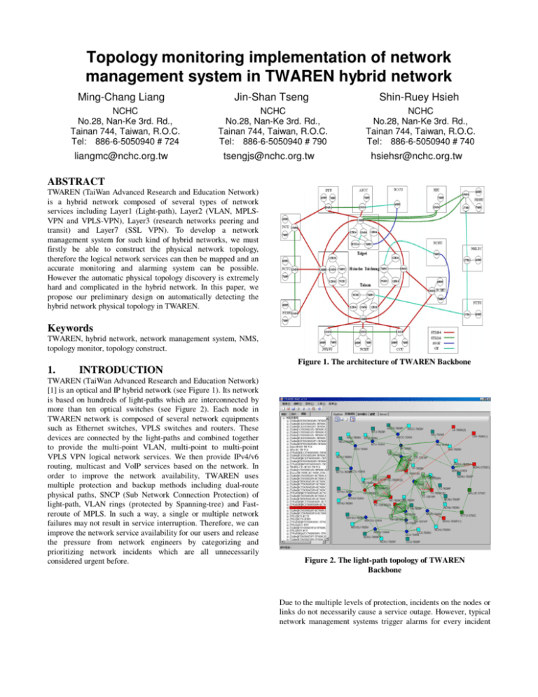
Topology monitoring implementation of network management system in TWAREN hybrid network Ming-Chang Liang NCHC No.28, Nan-Ke 3rd. Rd., Tainan 744, Taiwan, R.O.C. Tel: 886-6-5050940 # 724 liangmc@nchc.org.tw Jin-Shan Tseng Shin-Ruey Hsieh NCHC No.28, Nan-Ke 3rd. Rd., Tainan 744, Taiwan, R.O.C. Tel: 886-6-5050940 # 790 NCHC No.28, Nan-Ke 3rd. Rd., Tainan 744, Taiwan, R.O.C. Tel: 886-6-5050940 # 740 tsengjs@nchc.org.tw hsiehsr@nchc.org.tw ABSTRACT TWAREN (TaiWan Advanced Research and Education Network) is a hybrid network composed of several types of network services including Layer1 (Light-path), Layer2 (VLAN, MPLSVPN and VPLS-VPN), Layer3 (research networks peering and transit) and Layer7 (SSL VPN). To develop a network management system for such kind of hybrid networks, we must firstly be able to construct the physical network topology, therefore the logical network services can then be mapped and an accurate monitoring and alarming system can be possible. However the automatic physical topology discovery is extremely hard and complicated in the hybrid network. In this paper, we propose our preliminary design on automatically detecting the hybrid network physical topology in TWAREN. Keywords TWAREN, hybrid network, network management system, NMS, topology monitor, topology construct. 1. INTRODUCTION TWAREN (TaiWan Advanced Research and Education Network) [1] is an optical and IP hybrid network (see Figure 1). Its network is based on hundreds of light-paths which are interconnected by more than ten optical switches (see Figure 2). Each node in TWAREN network is composed of several network equipments such as Ethernet switches, VPLS switches and routers. These devices are connected by the light-paths and combined together to provide the multi-point VLAN, multi-point to multi-point VPLS VPN logical network services. We then provide IPv4/v6 routing, multicast and VoIP services based on the network. In order to improve the network availability, TWAREN uses multiple protection and backup methods including dual-route physical paths, SNCP (Sub Network Connection Protection) of light-path, VLAN rings (protected by Spanning-tree) and Fastreroute of MPLS. In such a way, a single or multiple network failures may not result in service interruption. Therefore, we can improve the network service availability for our users and release the pressure from network engineers by categorizing and prioritizing network incidents which are all unnecessarily considered urgent before. Figure 1. The architecture of TWAREN Backbone Figure 2. The light-path topology of TWAREN Backbone Due to the multiple levels of protection, incidents on the nodes or links do not necessarily cause a service outage. However, typical network management systems trigger alarms for every incident while some of them don't really affect the service quality. Immediate reporting on every non-severe incident will cause unnecessary burden on operation center engineers, which eventually becomes a waste of human resources and reduces the true value of the multiple level protection network itself. The management system needs to have the intelligence to distinguish and categorize the root cause of network incidents, thus proper reports can be generated smartly. However this is not a trivial task for an automatic system since the integration of information and problem identification is sometimes difficult to even experienced engineer. We have been continuously developing such an intelligent system. Before the system is fully mature and polished, we developed some supporting mechanisms and workarounds to mitigate the previously mentioned burden as much as possible. The fundamental solution to solve the problem is to make the system automatically detect the degree of influence caused by the network event. For example, the system has to decide whether or not the network event affected the service, the services that were affected and the degree of service impact, etc. Before it is possible, the topology relationship between the failed network components and their adjacent connected components must be determined first. However it is difficult to automatically discover the topology on a hybrid network like TWAREN. Traditional network spiders utilize Cisco Discovery Protocol (CDP) or fetch the configuration from network equipments to determine the network topology, which is not a feasible solution in a network composed of optical network equipments, MPLS and VLAN technologies. An automatic topology discovery method in such a hybrid network must be developed. In this paper, we will introduce our preliminary result on the development of the solution. 2. ISSUES One single circuit failure will at least causes the interfaces of the two ends to trigger alarms. Meanwhile, the affected upper layer services will also generate their respective alarms. Those scattered alarms will easily blur the key location and cause of the real problem. In a hybrid network like TWAREN, there are multiple underlying lightpaths and MPLS paths in the background. Any circuit or interface failure will affect a large number of logical network paths running on top of it, thus causing even more scattered alarms, making the problem identification even harder. The traditional topology of IP network components is no longer the effective way to help determining the fault location, therefore an automatic real topology monitoring solution covering all layer 1, 2 and 3 is necessary. With such a precise topology data, the relationship between interfaces and circuits, the affected services and the priority of the incident can then be determined in any failure. 3. DESIGN AND IMPLEMENTATION To construct the topology of network equipments and interfaces in TWAREN, a hybrid network topology construction method is proposed. To obtain the necessary topology information, the following techniques are used: (1) The network equipment configuration The running-configuration can usually be obtained from routers. After analyzing the running-configuration text, the interface IPs, forwarding information, MPLS and VPLS configuration can be extracted. This technique is extremely useful in identifying the topology of layer 3 connected equipments. However it is usually not so useful in scenarios with optical and MPLS network equipments and non-layer 3 connected equipments. (2) SNMP Besides some very low end switches, most network equipments provide SNMP interface. Variety information can be fetched by a standard Management Information Base (MIB) way. However, VLAN, MPLS and VPLS are not accessible by the standard MIB, which limits it use on these specific perspectives. We utilize MIB information to retrieve the line-card and interface statuses as well as the VLAN information to construct the VLAN topology. (3) Transaction Language 1 (TL1) Many type of information on optical network equipments cannot be obtained by MIB. In these cases the TL1 is used. However, different nomenclature of interface names, numbers and order are applied in TL1 and MIB technologies, which makes the situation much more complicated. We have to design corresponding rule to match the properties of TL1 and MIB for every single optical cards. In our design, TL1 provides the most information of the optical network topology. The first step of the construction of the network topology is to realize the physical connection relationship between network components. This is the most fundamental but hardest step in TWAREN hybrid network because the client edge (CE) interfaces of optical network equipments transparently process the optical signals without touching the ethernet frames. Thus all CDP packets will be ignored. The physical connection between ethernet and optical equipments is no way to detect. To minimize the impact of this information black hole, we identified those circuits manually and named them in such a way to reflect the two ends of the circuits. For example, the interface of the ethernet equipment ends will be named “TN7609P_1-12_TN15454_1-100-2_For-Research-Net”, which means the GE1/1/2 of the TN7609P connects to the CE1000-1/2 of the TN15454. Likewise, the interface of the optical equipment end is named “__TN7609P_1-1-2_ForResearch” to show that its opposite end connects to the GE-1/1/2 of TN7609P. The drawback of this technique is the increase of the load to maintain the network management. To mitigate this problem, we developed a graphic user interface to visually integrate the management work together, as shown in figure 3 and 4. Engineers only need to connect the two corresponding interfaces in the GUI, and then the names will be automatically generated by the system. Those names can also be modified manually afterward, as shown in figure 5. By this way, the relationship between optical and ethernet equipments can be identified, which makes the topology automatic discovery possible. The relationship between two optical equipments can be obtained directly by ONS TL1 commands. We use one TL1 command to discover all adjacent ONS, another TL1 command to show all the internal cross connections (e.g. vcM-vcN of Port A connects to vcP-vcQ of port B) and a final TL1 command to show all the outgoing cross connections (e.g. vcS-vcT of port C connects to the vcU-vcV of port D of another ONS). After all the optical circuit information is retrieved, a full optical lightpath map can be constructed, as shown in the figure 6. Combining the aforementioned naming and the optical topology automatic discovery, all ethernet equipments interconnected by optical networks can be fully resolved. Figure 3. Select the connection end point on the device panel. Figure 6. The path display of Ethernet link over light-path. Figure 4. Select the other end point of the connection. The next step is determining the relationship between ethernet equipments. Since the CDP protocol can be used to discover this relationship, only a simple MIB information retrieval can provide us the necessary information. After integrating the information together, the topology of ethernet equipments can be realized. Since we already have the optical-ethernet and the optical-optical topology, the topology from both technologies can be safely integrated without duplication. The last step is to deal with those equipments which don't support Cisco CDP or don't have interoperable CDP implementations. Since there is no way to discover the topology relationship between this kind of equipments, the aforementioned naming scheme is again used. Figure 5. Manually change the interface name on the GUI. After all physical interconnections have been identified; the upper layer logical network services can be easily mapped to the physical map to form a complete functional topology map. For example, to construct the VLAN topology map, the VLAN information can be obtained by the MIB retrieval. By analyzing the ports involved in each VLAN, the VLAN topology can be easily mapped onto the physical topology. Combining the STP status of each port, we can further know that whether the network segment is in the forward state or spanning-tree blocked state. The construction of the physical topology map is the very fundamental step of the success of the hybrid network management system. Once such physical topology is constructed, the monitoring of the upper layer services will be easy. The failure of network components can be easily located and the affect area determined. Thus all network failures can be categorized and prioritized. With the integration of the user information, the system will even be able to provide alarms to specific users whose required services are affected. layer 2 VPLS VPN can be constructed by mapping corresponding information to the physical topology. Therefore an intelligent monitoring and alarming system over logical network services will have a solid foundation to provide accurate pinpoint information. A customer based notification or a fully visual network monitoring system will then be possible. 5. REFERENCES [1] TaiWan Advanced Research and Education Network. http://www.twaren.net/english/. [2] Ming-Chang Liang, and Li-Chi Ku. Design and Implementation of TWAREN Hybrid Network Management System. APAN 26th, Aug 04~08, 2008. 4. CONCLUSION The key to develop a successful hybrid network management system is the ability of construct the physical topology of all network components. With this physical topology constructed, the upper layer logical topology, including layer 2 VLAN and [3] Ming-Chang Liang, Sheng-I Chang, Meng-Chang Lin and Chen-Tsai Chiang. The advanced implementation of network management system with fault detection in TWAREN hybrid network. APAN 28th, July 20-23, 2009.


