Series circuits
advertisement
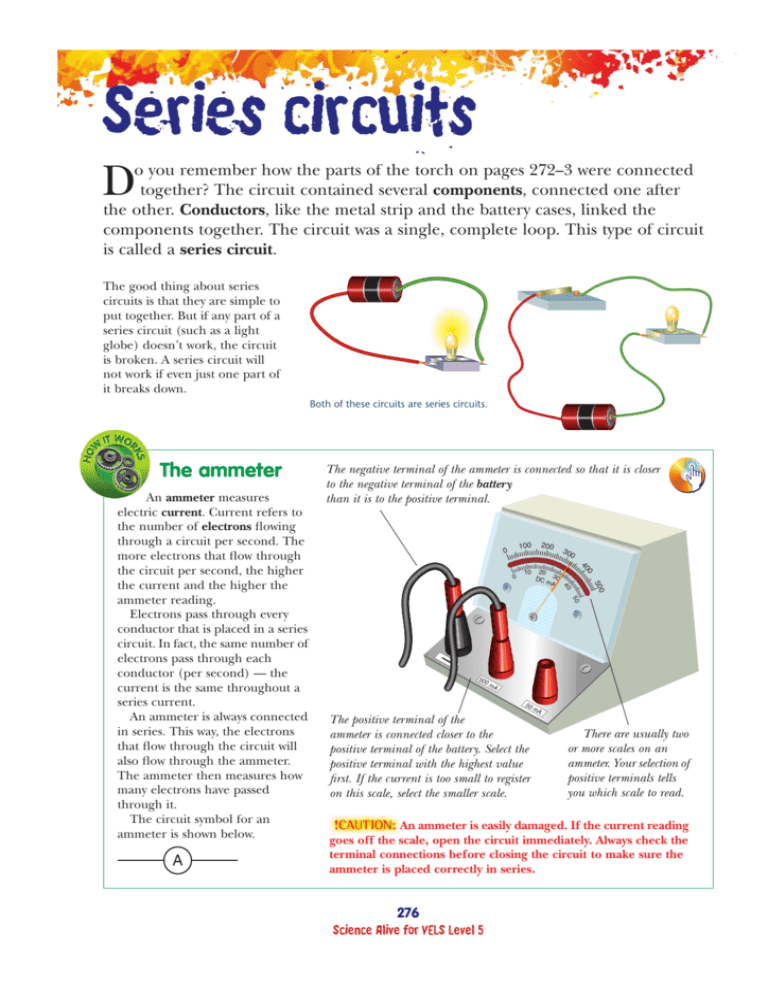
Series circuits D o you remember how the parts of the torch on pages 272–3 were connected together? The circuit contained several components, connected one after the other. Conductors, like the metal strip and the battery cases, linked the components together. The circuit was a single, complete loop. This type of circuit is called a series circuit. The good thing about series circuits is that they are simple to put together. But if any part of a series circuit (such as a light globe) doesn’t work, the circuit is broken. A series circuit will not work if even just one part of it breaks down. Both of these circuits are series circuits. The ammeter 30 0 500 20 DC 30 mA 0 0 10 40 50 A 200 100 0 40 An ammeter measures electric current. Current refers to the number of electrons flowing through a circuit per second. The more electrons that flow through the circuit per second, the higher the current and the higher the ammeter reading. Electrons pass through every conductor that is placed in a series circuit. In fact, the same number of electrons pass through each conductor (per second) — the current is the same throughout a series current. An ammeter is always connected in series. This way, the electrons that flow through the circuit will also flow through the ammeter. The ammeter then measures how many electrons have passed through it. The circuit symbol for an ammeter is shown below. The negative terminal of the ammeter is connected so that it is closer to the negative terminal of the battery than it is to the positive terminal. — 50 0m A 50 The positive terminal of the ammeter is connected closer to the positive terminal of the battery. Select the positive terminal with the highest value first. If the current is too small to register on this scale, select the smaller scale. mA There are usually two or more scales on an ammeter. Your selection of positive terminals tells you which scale to read. An ammeter is easily damaged. If the current reading goes off the scale, open the circuit immediately. Always check the terminal connections before closing the circuit to make sure the ammeter is placed correctly in series. 276 Science Alive for VELS Level 5 ! A series of batteries Many portable CD players, calculators and toys run on more than one battery. If this is the case, the batteries are likely to be connected one after the other, in series. When batteries are connected in series, electrons flowing through the circuit must flow through each battery. The electrons are given electrical energy from each battery. REMEMBER 1. Describe how the components in a series circuit are arranged. 2. To which terminal of a battery should the positive terminal of an ammeter be connected? 3. Why is it important to check the connections to an ammeter before closing the circuit? 4. The two circuits below contain identical globes and batteries. What should the reading of the ammeter in the second circuit be? Explain your answer. The two batteries in this case are 1.5 V each. In total, these batteries provide 3 V of energy to the electrons flowing through them. Note that the positive terminal of one battery is joined to the negative terminal of the other. Batteries must always be connected this way. Using an ammeter You will need: 6 V battery or other power supply ammeter 2 light globes (6 V) switch connecting wires. • Connect a series circuit that contains a battery, an ammeter, a switch, two globes and connecting wires. Remember to check that the A terminals are connected correctly. Connect to the highest scale of the ammeter first. A 10 mA 1. (a) What is the reading on the ammeter before the switch is closed? (b) How much current is flowing through the circuit before the switch is closed? A • Complete the circuit by closing the switch. Record the reading shown on the ammeter. • Change the circuit so that the ammeter is in the position shown in the diagram at right. 5. What is a disadvantage of connecting circuit components in series? • Close the switch. Record the ammeter reading. PREDICT 2. What do you notice about the ammeter reading in the second position? 6. Predict what would happen to globe A if globe B ‘blew’ in this circuit. A B • Predict the reading on the ammeter if it were to be placed in the position shown in the diagram below. • Test your prediction. • Compare your results with those of other members of the class. What do you notice? A 277 12. Electrical energy ✓ learning 3. Complete this sentence: The current in a series circuit . A I CAN: describe what a series circuit is connect batteries and other components in series describe a disadvantage of series circuits. ! Parallel circuits magine what would happen if the electrical appliances in your home were all connected in series? Every time a light blows out, no other electrical appliance would work. A series circuit will not work if a part of the circuit breaks. To avoid this problem, most circuits are connected in parallel. A parallel circuit works even when one part of it breaks down. I At this point, the electrons can either move along the first path or the second path. If the paths are identical, half of the electrons will take the first path and the other half will take the second path. Although the number of electrons is divided between the two paths, each electron will continue to carry the same amount of energy (voltage). Second path First path A parallel circuit drawn as a circuit diagram. A parallel circuit has more than one path for the electricity to follow. If one of the paths has a break in it, the other paths will still work. Only appliances in the broken part of the circuit will stop working. The voltmeter The voltmeter tells us how much of the electron’s energy is turned into light energy. This light globe uses almost all of the total energy given to the electrons. This battery gives 6 V of energy to the electrons as they leave the negative terminal of the battery. 6V – + 5 0 10 0 1 Volt s 2 15 3 The energy of electrons moving around a circuit comes from a battery or other power supply. As the electrons move around the circuit, some of their energy is transformed into other forms of energy by the appliances in the circuit. The energy that is transformed along the circuit is measured in volts with a voltmeter. Like an ammeter, a voltmeter is placed in a circuit with its positive terminal closer to the positive terminal of the power supply than the negative terminal. But, unlike an ammeter, a voltmeter is connected in parallel to the appliances in a circuit. The symbol for a voltmeter is shown below. V Electrons Electrons — 15 v 3v Voltmeters measure how much energy the electrons lose as they pass through the appliance. 278 Science Alive for VELS Level 5 ! REMEMBER 1. What unit is electrical energy measured in? 2. When a voltmeter is used to take readings of an appliance, is it placed in series or parallel with the appliance? 3. To which terminal of the battery is the negative terminal of a voltmeter connected more closely? THINK 4. In the experiment ‘Parallel circuits’, why did the remaining light globes still work when one was removed? 5. If a 9 V battery is used to power a circuit with four globes in parallel to each other, how many volts of electrical energy will each globe receive? 6. A battery is connected to two identical globes that are connected in parallel. The current flowing through one globe is 400 mA. What current flows through: (a) the other globe? (b) the battery? 7. Why are all of the appliances in a house connected in parallel? These lights are connected in parallel. Why? Parallel circuits You will need: 6 V battery or power supply 3 light globes (6 V) switch connecting wires. • Connect the circuit as shown in the diagram at right. • Close the switch. Record the reading on the voltmeter. SKILL BUILDER 8. Using the correct symbols, draw this circuit as a circuit diagram. V • Disconnect the voltmeter. Reconnect it across the next globe as shown in the diagram below. • Close the switch. Record the reading shown on the voltmeter. 5 0 • Repeat the process for the third globe. 2 15 3 15 v 3v V 4. Complete this sentence: The voltage through each branch of a parallel circuit is . 279 12. Electrical energy ✓ learning 9. (a) Use the correct symbols to draw a circuit diagram containing two light globes in parallel with each other. Make sure you include a battery in your circuit diagram. (b) Redraw the circuit so that a single switch turns the whole circuit on or off. (c) Redraw the circuit with switches placed so that the light globes can be turned on separately. • Remove one of the globes. 3. Compare the readings on the voltmeter in this experiment with the voltage of the battery or power source used. What do you find? 1 Volts — 1. How did the readings on the voltmeter change for each globe? 2. Do the remaining globes still work if one globe is removed? 10 0 I CAN: use a voltmeter to measure the energy transformed by an appliance describe and construct simple parallel circuits. ! Comparing circuits ave you ever connected last year’s Christmas lights only to find that they don’t work? You’re sure that they are plugged in and that the switch is closed, but still nothing happens. It could be that the globes are connected in series and one globe has burnt out. Now comes the tricky part, finding out which globe has burnt! Not all Christmas lights are connected in series. Those connected in parallel will still work even if some of the globes have burnt out. And it’s easy to tell which globes need to be replaced. H Comparing circuits You will need: 3 identical light globes 6 V battery switch PART B • Connect a parallel circuit like the one shown. connecting wires voltmeter burnt-out light globe. • Close the switch. Note the brightness of the globes. PART A • Connect a series circuit with three identical, working globes, a battery and a switch. • Use a voltmeter to measure the energy used by each of the globes. Complete a table like the one shown below. A B C Globe • Close the switch. Note the brightness of the globes. B C Reading on voltmeter (V) A • Use a voltmeter to measure the amount of energy used by each globe. Record the voltage in a table like the one below. Globe A B C Reading on voltmeter (V) 4. How does the energy used by each globe in a parallel circuit differ from the energy used by each globe in a series circuit? A B 5. How does the brightness of the globes in the parallel circuit differ from the globes in series? C • Replace one of the globes with the burnt-out globe. • Close the switch. • Replace one of the globes in the parallel circuit with the burnt-out globe. Close the switch. 1. Describe what happens in the circuit with the burntout globe. 6. Describe what happens in the parallel circuit when one light globe does not work. 2. How much current flows through the series circuit containing the burnt-out globe? 7. How does the brightness of the remaining globes change? • Remove the burnt-out globe and one of the working globes. 8. List two advantages of a parallel circuit over a series circuit. 3. How does the brightness of one globe compare with the brightness of three globes in series? 9. Give one advantage of a series circuit over a parallel circuit. 280 Science Alive for VELS Level 5 ! Go to worksheet 12.3: Modelling circuits What affects brightness? The brightness of each globe depends on both the voltage and the electric current. The experiment on page 280 shows how voltage affects the brightness of globes. In series circuits, the electrons share their energy (voltage) among all of the globes in the circuit. The more globes there are, the more the energy needs to be shared and the less brightly they glow. The branches of a parallel circuit do not share the energy carried by each electron. So, identical globes placed in parallel glow A 60 watt globe with equal brightness. No matter how many branches are added to a parallel circuit, the brightness of each identical globe is the same. What about in your home? All globes are connected in parallel, but because they are not all identical, some may glow more brightly than others. The electrons flowing through each globe receive the same amount of energy. Voltage is a measure of how much energy electrons receive — for homes in Australia, it’s 240 V. However, some globes allow more electrons through than others. REMEMBER 1. Why are the appliances in houses and other buildings connected in parallel? Give at least two reasons. 2. Describe a disadvantage of parallel circuits. 3. What do numbers printed on a globe refer to — for example, 80 W? 4. Why does a 70 W globe glow more brightly than a 60 W globe, even though each electron passing through them receives the same amount of energy? THINK 5. Describe how the brightness of a globe is affected by: (a) voltage (b) current. SKILL BUILDER 6. Are the circuits below the same or different? Explain your answer. The numbers printed on light globes tell us how quickly the globes use energy. A 75 watt (W) light globe uses energy more quickly than a 60 W light globe. The electrons that pass through these globes carry the same amount of energy (240 V). But more electrons pass through the 75 W globe than the 60 W globe in any given time to supply energy more quickly. So, current, as well as voltage, affects brightness. (Remember that current refers to the number of electrons flowing through a circuit per second.) Christmas lights — if these lights are connected in parallel, when one light blows out, the others still work. 281 12. Electrical energy ✓ learning A 75 watt globe I CAN: explain how voltage affects brightness explain how current affects brightness. !


