Basic Stress Equations
advertisement
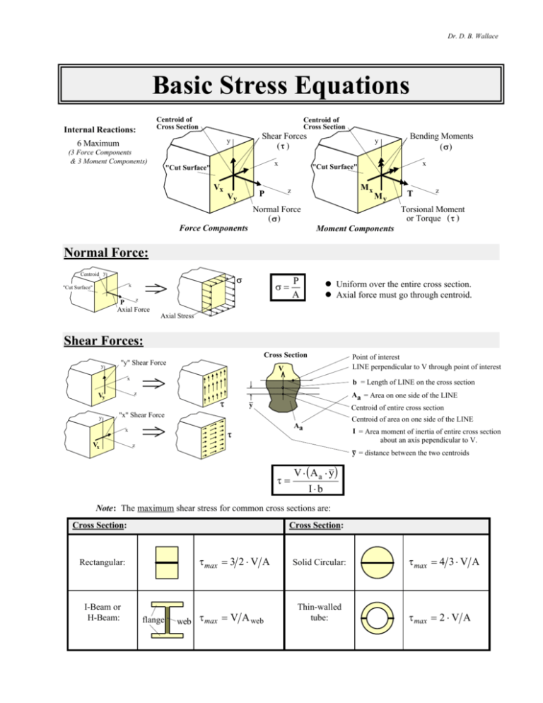
Dr. D. B. Wallace Basic Stress Equations Centroid of Cross Section Internal Reactions: Centroid of Cross Section Shear Forces (τ ) y 6 Maximum (3 Force Components & 3 Moment Components) x "Cut Surface" Vx Bending Moments (σ) x "Cut Surface" Mx z P Vy y My Normal Force (σ) T z Torsional Moment or Torque ( τ ) Force Components Moment Components Normal Force: Centroid y σ x "Cut Surface" P A σ= z P Axial Force l Uniform over the entire cross section. l Axial force must go through centroid. Axial Stress Shear Forces: Cross Section y "y" Shear Force Point of interest LINE perpendicular to V through point of interest V x Vy y b = Length of LINE on the cross section z τ Aa = Area on one side of the LINE Centroid of entire cross section y "x" Shear Force Vx Centroid of area on one side of the LINE Aa τ x I = Area moment of inertia of entire cross section about an axis pependicular to V. z y = distance between the two centroids τ= b V ⋅ Aa ⋅ y I⋅b g Note: The maximum shear stress for common cross sections are: Cross Section: Cross Section: τ max = 3 2 ⋅ V A Rectangular: I-Beam or H-Beam: flange web τ max = V A web Solid Circular: Thin-walled tube: τ max = 4 3 ⋅ V A τ max = 2 ⋅ V A Basic Stress Equations Dr. D. B. Wallace Torque or Torsional Moment: Solid Circular or Tubular Cross Section: y τ= x "Cut Surface" z T Torque τ max = τ max = T⋅r J τ 16 ⋅ T π ⋅ D3 16 ⋅ T ⋅ Do e j J= J= for solid circular shafts π ⋅ Do 4 − D i 4 r = Distance from shaft axis to point of interest R = Shaft Radius D = Shaft Diameter π ⋅ D4 π ⋅ R 4 = 32 2 e π ⋅ Do4 − Di4 for solid circular shafts j 32 for hollow shafts for hollow shafts Rectangular Cross Section: τ2 y Cross Section: b Centroid τ1 x "Cut Surface" z T Torque Note: a>b a Torsional Stress Method 1: b τ max = τ1 = T ⋅ 3 ⋅ a + 1.8 ⋅ b g ea 2 ⋅ b2 j ONLY applies to the center of the longest side Method 2: τ1,2 = T α1,2 ⋅ a ⋅ b 2 Use the appropriate α from the table on the right to get the shear stress at either position 1 or 2. a/b 1.0 1.5 2.0 3.0 4.0 6.0 8.0 10.0 ∞ Other Cross Sections: Treated in advanced courses. 2 α1 .208 .231 .246 .267 .282 .299 .307 .313 .333 α2 .208 .269 .309 .355 .378 .402 .414 .421 ---- Basic Stress Equations Dr. D. B. Wallace Bending Moment "x" Bending Moment y x Mx σ= σ z Mx ⋅ y Ix and σ= My ⋅ x Iy "y" Bending Moment y where: Mx and My are moments about indicated axes y and x are perpendicular from indicated axes Ix and Iy are moments of inertia about indicated axes x z My σ Moments of Inertia: b b ⋅ h3 I= 12 c h D h is perpendicular to axis c R b ⋅ h2 I = c 6 Z= I = π ⋅ D4 π ⋅ R4 = 64 4 Z = I π ⋅ D3 π ⋅ R3 = = c 32 4 Parallel Axis Theorem: I = Moment of inertia about new axis I = Moment of inertia about the centroidal axis A = Area of the region d = perpendicular distance between the two axes. new axis Area, A d I = I + A ⋅d2 centroid Maximum Bending Stress Equations: σ max = M⋅c M = I Z σ max = 32 ⋅ M π⋅D 3 bSolid Circular g σ max = 6⋅ M b ⋅ h2 a Rectangular f The section modulus, Z, can be found in many tables of properties of common cross sections (i.e., I-beams, channels, angle iron, etc.). Bending Stress Equation Based on Known Radius of Curvature of Bend, ρ. The beam is assumed to be initially straight. The applied moment, M, causes the beam to assume a radius of curvature, ρ. Before: σ = E⋅ After: y ρ E = Modulus of elasticity of the beam material M ρ y = Perpendicular distance from the centroidal axis to the point of interest (same y as with bending of a straight beam with Mx). M ρ = radius of curvature to centroid of cross section 3 Basic Stress Equations Dr. D. B. Wallace Bending Moment in Curved Beam: Geometry: σo nonlinear stress distribution centroid centroidal axis y co e ci σi rn neutral axis ρ r ri A dA area ρ e = r − rn rn = ro z A = cross sectional area rn = radius to neutral axis r = radius to centroidal axis e = eccentricity M Stresses: Any Position: σ= Inside (maximum magnitude): −M ⋅ y e ⋅ A ⋅ rn + y b σi = g Outside: M ⋅ ci e ⋅ A ⋅ ri σo = − M ⋅ co e ⋅ A ⋅ ro Area Properties for Various Cross Sections: Cross Section Rectangle r ρ z r ri + t dA ρ A FG r IJ Hr K h⋅t area h 2 t ⋅ ln o i ri h ro Trapezoid r ρ ti ri ri + to h ro Hollow Circle r a ρ b h ⋅ ti + 2 ⋅ to 3⋅ t i + t o b g g to − ti + For triangle: set ti or to to 0 r 2⋅π b 4 LM N FG IJ H K ro ⋅ t i − ri ⋅ t o r ⋅ ln o h ri r 2 − b2 − r 2 − a 2 OP Q h⋅ e ti + t o 2 π ⋅ a 2 − b2 j Basic Stress Equations Dr. D. B. Wallace Bending Moment in Curved Beam (Inside/Outside Stresses): Stresses for the inside and outside fibers of a curved beam in pure bending can be approximated from the straight beam equation as modified by an appropriate curvature factor as determined from the graph below [i refers to the inside, and o refers to the outside]. The curvature factor magnitude depends on the amount of curvature (determined by the ratio r/c) and the cross section shape. r is the radius of curvature of the beam centroidal axis, and c is the distance from the centroidal axis to the inside fiber. Centroidal Axis c r M⋅c I Inside Fiber: σ i = Ki ⋅ Outside Fiber: σ o = Ko ⋅ M M⋅c I B A b/8 4.0 B A b b/4 c Values of Ki for inside fiber as at A 3.5 B B A A c U or T 3.0 b/2 Curvature Factor Round or Elliptical b A B c 2.5 Trapezoidal b/3 b/6 2.0 B b B A A c I or hollow rectangular Ki M r 1.5 1.0 Ko I or hollow rectangular U or T 0.5 Values of Ko for outside fiber as at B Round, Elliptical or Trapezoidal 0 1 2 3 4 5 6 7 Amount of curvature, r/c 5 8 9 10 11


