Reference Manual
00809-0100-4016, Rev DA
September 2010
Sanitary Tank Spud
Sanitary Tank Spud Weld Guidelines
This document is a welding guideline. Actual procedures and specifications
vary based upon equipment and application.
This guideline is intended to provide general guidance only to achieve an
acceptable installation of a Rosemount sanitary tank spud in order to mitigate
potential costly rework. It will discuss ways to minimize potential distortion of
the tank spud via tank preparation and welding practices. Employ a skilled,
experienced welder to achieve best results.
TANK PREPARATION
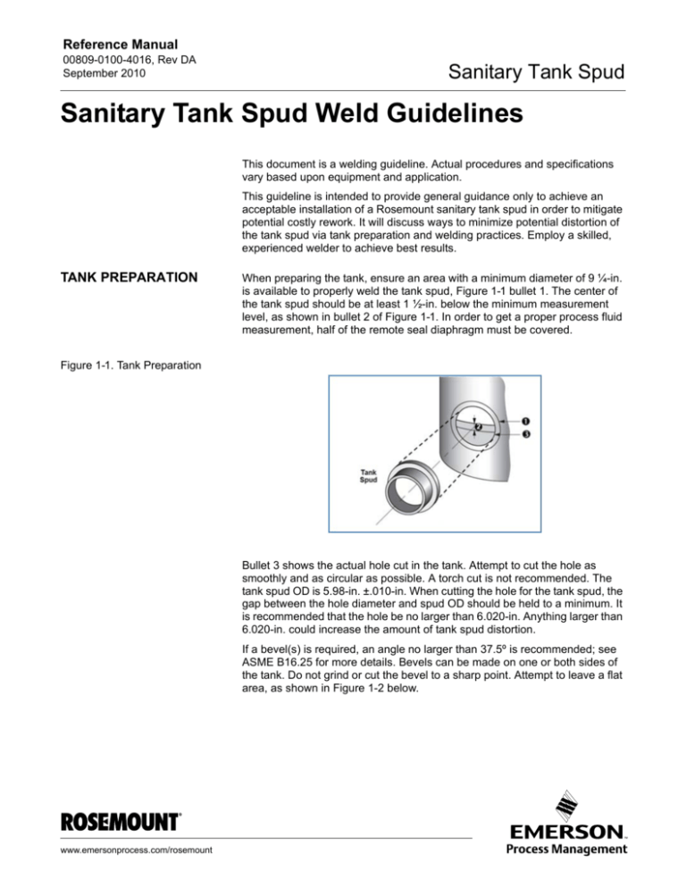
When preparing the tank, ensure an area with a minimum diameter of 9 ¼-in.
is available to properly weld the tank spud, Figure 1-1 bullet 1. The center of
the tank spud should be at least 1 ½-in. below the minimum measurement
level, as shown in bullet 2 of Figure 1-1. In order to get a proper process fluid
measurement, half of the remote seal diaphragm must be covered.
Figure 1-1. Tank Preparation
Bullet 3 shows the actual hole cut in the tank. Attempt to cut the hole as
smoothly and as circular as possible. A torch cut is not recommended. The
tank spud OD is 5.98-in. ±.010-in. When cutting the hole for the tank spud, the
gap between the hole diameter and spud OD should be held to a minimum. It
is recommended that the hole be no larger than 6.020-in. Anything larger than
6.020-in. could increase the amount of tank spud distortion.
If a bevel(s) is required, an angle no larger than 37.5º is recommended; see
ASME B16.25 for more details. Bevels can be made on one or both sides of
the tank. Do not grind or cut the bevel to a sharp point. Attempt to leave a flat
area, as shown in Figure 1-2 below.
www.emersonprocess.com/rosemount
Reference Manual
Sanitary Tank Spud
00809-0100-4016, Rev DA
September 2010
Figure 1-2. Bevel Example
The flat area should be large enough to minimize spud distortion but small
enough so that tank weld requirements can be met. Minimizing the bevel
angle will decrease the amount of fill required during weld and minimize the
number of weld passes. These best practices will decrease heat input and
help mitigate distortion.
WELDING
Excessive heat will distort the tank spud. Allow adequate cooling time between passes.
Ensure spud is not assembled to transmitter and/or remote seal prior to
welding.
Do not nick the sealing surfaces of the tank spud, the inner angled surfaces
where the o-ring sits shown in Figure 1-3, as any irregularities may cause
leaks.
Figure 1-3. O-ring Sealing
Surfaces
1-2
Reference Manual
00809-0100-4016, Rev DA
September 2010
Sanitary Tank Spud
With the spud centered in the tank hole, make sure the inner surface of the
spud is flush with the inner surface of the tank. The leak detection hole in the
spud should be at the bottom of the spud. With the spud properly located, tack
weld it into place using 4 tack welds, 90º from each other.
Begin welding on the inside of vessel. Weld in sections similar to the
sequence in Figure 1-4.
Figure 1-4. Welding Sections
Diagram
Allow time to cool between weld sections. Weld should be cooled to 350º F or
less after each pass while being cool to the touch is preferred. Use of a damp
cloth or compressed air is allowed if rapid cooling is desired.
Repeat procedure on the outside of the tank.
NOTE:
The number of weld passes should be kept to a minimum while maintaining
tank weld standards and sanitary requirements. Additional weld passes are a
significant contributor to spud distortion due to additional heat input and
added filler material in beveled area of hole. When fill passes are required, a
1/16-in. diameter weld rod is recommended.
1-3
Reference Manual
00809-0100-4016, Rev DA
September 2010
Sanitary Tank Spud
Standard Terms and Conditions of Sale can be found at www.rosemount.com\terms_of_sale
The Emerson logo is a trade mark and service mark of Emerson Electric Co.
Rosemount and the Rosemount logotype are registered trademarks of Rosemount Inc.
Coplanar is a trademark of Rosemount Inc.
PlantWeb is a mark of one of the Emerson Process Management companies.
HART is a registered trademark of the HART Communications Foundation.
FOUNDATION fieldbus is a registered trademark of the Fieldbus Foundation.
All other marks are the property of their respective owners.
©2010 Rosemount Inc. All rights reserved.
Emerson Process Management
Rosemount Measurement
8200 Market Boulevard
Chanhassen MN 55317 USA
Tel (USA) 1 800 999 9307
Tel (International) +1 952 906 8888
Fax +1 952 949 7001
00809-0100-4016 Rev DA, 9/10
Emerson Process Management
Blegistrasse 23
P.O. Box 1046
CH 6341 Baar
Switzerland
Tel +41 (0) 41 768 6111
Fax +41 (0) 41 768 6300
Emerson FZE
P.O. Box 17033
Jebel Ali Free Zone
Dubai UAE
Tel +971 4 811 8100
Fax +971 4 886 5465
Emerson Process Management Asia Pacific
Pte Ltd
1 Pandan Crescent
Singapore 128461
Tel +65 6777 8211
Fax +65 6777 0947
Service Support Hotline : +65 6770 8711
Email : Enquiries@AP.EmersonProcess.com

