design of virtual models of mechatronics systems with simulink 3d
advertisement

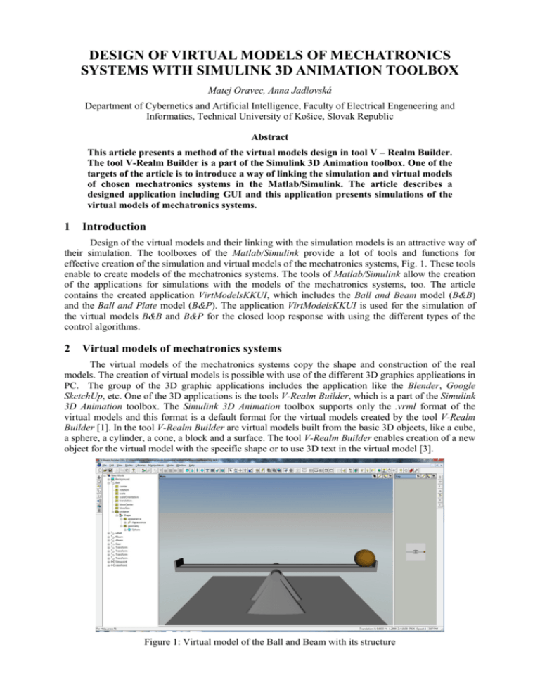
DESIGN OF VIRTUAL MODELS OF MECHATRONICS SYSTEMS WITH SIMULINK 3D ANIMATION TOOLBOX Matej Oravec, Anna Jadlovská Department of Cybernetics and Artificial Intelligence, Faculty of Electrical Engeneering and Informatics, Technical University of Košice, Slovak Republic Abstract This article presents a method of the virtual models design in tool V – Realm Builder. The tool V-Realm Builder is a part of the Simulink 3D Animation toolbox. One of the targets of the article is to introduce a way of linking the simulation and virtual models of chosen mechatronics systems in the Matlab/Simulink. The article describes a designed application including GUI and this application presents simulations of the virtual models of mechatronics systems. 1 Introduction Design of the virtual models and their linking with the simulation models is an attractive way of their simulation. The toolboxes of the Matlab/Simulink provide a lot of tools and functions for effective creation of the simulation and virtual models of the mechatronics systems, Fig. 1. These tools enable to create models of the mechatronics systems. The tools of Matlab/Simulink allow the creation of the applications for simulations with the models of the mechatronics systems, too. The article contains the created application VirtModelsKKUI, which includes the Ball and Beam model (B&B) and the Ball and Plate model (B&P). The application VirtModelsKKUI is used for the simulation of the virtual models B&B and B&P for the closed loop response with using the different types of the control algorithms. 2 Virtual models of mechatronics systems The virtual models of the mechatronics systems copy the shape and construction of the real models. The creation of virtual models is possible with use of the different 3D graphics applications in PC. The group of the 3D graphic applications includes the application like the Blender, Google SketchUp, etc. One of the 3D applications is the tools V-Realm Builder, which is a part of the Simulink 3D Animation toolbox. The Simulink 3D Animation toolbox supports only the .vrml format of the virtual models and this format is a default format for the virtual models created by the tool V-Realm Builder [1]. In the tool V-Realm Builder are virtual models built from the basic 3D objects, like a cube, a sphere, a cylinder, a cone, a block and a surface. The tool V-Realm Builder enables creation of a new object for the virtual model with the specific shape or to use 3D text in the virtual model [3]. Figure 1: Virtual model of the Ball and Beam with its structure The first of presented virtual models is the mechatronic model Ball and Beam (B&B). The model B&B is similar with other mechatronics models of this type and dimensions of the model B&B are used from the real model Humusoft CE151 in the direction of the axis x [5]. The model B&B is created from basic shapes like a cube, a sphere, a block and its structure is shown on the Fig. 1. The second virtual model is the mechatronic system Ball and Plate (B&P). Design of the model B&P is based on the construction of the real model B&P_KYB. The model B&P_KYB is situated in Laboratory of the mechatronics systems V142, Department of Cybernetics and Artificial Intelligence, Faculty of Electrical Engineering and Informatics, Technical University of Košice, (http://kyb.fei.tuke.sk/laboratoria/miest/V142.php) [3]. The virtual model of the B&P and its structure is shown on Fig. 2. Figure 2: Virtual model of the Ball and Plate and its structure Connection of the simulation and virtual model created a more illustrative final model for the graphical representation of the chosen process variables. The simulation process is shown by the animation of the virtual model. Chosen variable isn’t illustrated only like a graph, but like an animation of the parts of the virtual model. For the correct simulation limits of the important variables should be implemented. The correct design and linking of the simulation and virtual model should ensure very similar results of the simulation of the real and virtual model. 3 Simulation models of mechatronics systems in Matlab/Simulink For creating simulation models of the dynamic systems is a mathematical formulation of the mechatronics systems B&B and B&P very important, what is expressed by equations (1), (2), (3), (4), (5), (6). In the Matlab tool the models of the mechatronics systems are implemented in form of the functions and scripts. In the Simulink tool the models B&B and B&P are implemented in form of the function schemes, which are consisting of the several connected blocks. The mathematic formulation of the model B&B based on the physical laws is divided to two subsystems, the first subsystem is the Ball and Beam and second subsystem is the Servomotor [3]. The subsystem Ball and Beam is described by nonlinear differential equation: y(t ) g sin (t ) 2D 2 1 5( D 2 d 2 ) (1) The subsystem Servomotor is described by linear differential equation: (t ) Ks (u s (t ) (t )) Ts Parameters and variables of the model B&B are listed in Tab. 1, created m – files of the simulation model B&B in tool Matlab are listed in Tab. 2. Structure of the simulation model in the Simulink tool (2) is shown on Fig. 3. Constraints of the mechatronic model B&B are included in simulation and virtual model of B&B. Table 1: PHYSICAL VARIABLES AND PARAMETERS OF MODEL B&B LABEL y(t) α(t) us(t) D d Ks Ts DESCRIPTION ball position beam angle voltage of servomotor ball radius distance of the left and right part of the beam servomotor gain time constant of servomotor VALUE 0,03 UNITS [m] [rad] [V] [m] 0,01 [m] 0,1878 0,1878 - Table 2: STRUCTURE OF THE SIMULATION MODEL B&B IN MATLAB NAME main.m coeffs.m nlBallBeam.m ssBallBeam.m tfBallBeam.m paramPolyC.m paramLqsC.m paramGpcC.m paramMpcC.m PolyC.m, LqsC.m,LqC.m, GpcC.m, MpcC.m initWrlWorld.m drawWrlWorld.m DESCRIPTION main script script with model parameters nonlinear model B&B state space of model B&B transform function of model B&B calculation of polynomial control algorithm parameters – pole placement method calculation of parameters of state discrete LQI control algorithm calculation of parameters of predictive GPC control algorithm calculation of parameters of predictive MPC control algorithm implement control algorithm virtual model initialization animation of virtual model Figure 3: Simulink scheme of the B&B model with block of the virtual model The next presented model is the simulation model of B&P, which is derived from the real model B&P_KYB. Mathematic formulation of the model B&P based on the physical laws is divided to two subsystems, too. The first subsystem is the Ball and Plate and the second subsystem is the Servomotors [3]. The subsystem Ball and Plate is described by two nonlinear differential equations: 5 g sin (t ) 7 5 y y (t ) g sin (t ) 7 yx (t ) (3) (4) The subsystem Servomotors is described by two linear differential equations: Kx ( ref (t ) (t )) Tsx Ky (t ) ( ref (t ) (t )) Tsy (t ) (5) (6) Parameters and variables of the model B&P are listed in Tab. 3, created m – files of the simulation model B&B in the Matlab tool have similar structure and functionality like in the model B&B, listed in Tab. 2. Structure of the simulation model B&P in the Simulink tool is shown in Fig. 4. Constraints of the mechatronic model B&P are included in simulation and virtual model of the B&P. Table 3: PHYSICAL VARIABLES AND PARAMETERS OF MODEL B&P LABEL yx(t) yy(t) αref(t) α(t) βref(t) β(t) Ksx Tsx Ksy Tsy DESCRIPTION ball position – axis x ball position – axis y reference angle – axis x plate tilt – axis x reference angle – axis y plate tilt – axis y servomotor gain – axis x time constant of servomotor – axis x servomotor gain – axis y time constant of servomotor – axis y UNITS [m] [m] [rad] [rad] [rad] [rad] - Figure 4: Simulink scheme of the B&P model with block of the virtual model 4 Virtual Models B&B and B&P using Matlab To simplify the parameters settings of the virtual models simulations, the Matlab application was created, called VirtModelsKKUI, Fig. 5. Figure 5: Application with Virtual Model B&B The application VirtModelsKKUI is used for presentation of the both virtual models, B&B and B&P, which are presented in this article. The control algorithms of the mechatronics systems (described in this article) are implemented in control structure and for the control are used optimal state, polynomial and predictive control algorithm. The control algorithms are used for simulation. Main window of the application VirtModelsKKUI gives user option to choose the model, to set simulation parameters and to choose controller algorithm type, Fig. 5. At the right part of GUI is place for graph of the ball position and input voltage. After the pushing button „Simulation“, a new window opens with virtual model and graphs of the actual ball position and reference trajectory, Fig. 6. Window of the application VirtModelsKKUI is refreshed every sample period. At the end of the simulation the window is closed and result of the simulation is shown in the graph form in main window of the application VirtModelsKKUI. Connection of the simulation and virtual model is in the Matlab tool realized by instruction set, which is used for the virtual model animation. Example of source code is shown on Fig. 7. Figure 6: GUI of Virtual Simulation Model B&P during the running simulation Figure 7: A part of source code for animation of the virtual model 5 Virtual Models B&B and B&P using Simulink Designed simulation model in the tool Simulink is extended by set of buttons, which allow user to change the controller types and initialize the model parameters. The virtual models in the Simulink are in separate .mdl files, which contain closed loop schemes of the models B&B and B&P. For defined control target are used continuous PID regulators and discrete PSD regulators. User selects a type of the control, the method of control synthesis and the reference trajectory by double clicks on chosen button, Fig. 8. The virtual model is opened, if user selects a block of virtual model by the double click. Results of the time responses are shown in the blocks called Output x, Output y a XY Graph. Figure 8: Virtual model of the Ball and Plate in control scheme Connection of the simulation and the virtual model is realized in the tool Simulink by the block VR Sink. This block contains a root folder of the virtual model and enables to choose parts of the model, which should be animated. Created virtual models are used for testing and comparison of the designed control algorithms and for interactive presentation of the Laboratory of the mechatronics systems V142, Department of Cybernetics and Artificial Intelligence, Faculty of Electrical Engineering and Informatics, Technical University of Košice, (http://kyb.fei.tuke.sk/laboratoria/miest/V142.php) [3]. View of the virtual model simulation with the time response of the monitored physical variables is for user more valuable, like the simulation of the simple, none virtual model. 6 Conclusion This article presents a way of design of the simulation models and the virtual models of the mechatronics systems, also presents a way of linking models in the Matlab and Simulink tools. The article presents the created application VirtModelsKKUI in Matlab tool and virtual models in Simulink tool. This applications are used for the simulation of the virtual models B&B and B&P. The virtual models B&B and B&P provide more illustrative view of the simulation with control algorithms in chosen control scheme. Designed virtual models are used for the presentation of control algorithms in case, that the real model is not available. Description of the real model B&P_KYB is on web page http://kyb.fei.tuke.sk/laboratoria/modely/gnk.php. The virtual models of mechatronics systems are designed to be use in teaching process of subjects Optimal and nonlinear systems and Control and arficial intelligence, for the experiments with classical or modern control methods. Acknowledgements This contribution is the result of the Vega project implementation – Dynamic Hybrid Architectures of the Multi-agent Network Control Systems (No. 1/0286/11), supported by the Scientific Grant Agency of Slovak Republic – 40%, and of the Research and Development Operational Program for project: University Science Park Technicom for innovative applications with knowledge technology support, (ITMS code 26220220182), co-financed by the ERDF – 60%. References [1] Virtual Reality Toolbox User’s Guide. HUMUSOFT s.r.o. and The MathWorks, Inc., 2001 - 2004. Web: http://www.mathworks.com/help/releases/R13sp2/pdf_doc/vr/vr.pdf [2] Creating Graphical User Interfaces (User’s guide). HUMUSOFT s.r.o. and The MathWorks, Inc., 2000 - 2014. Web: http://www.mathworks.com/help/pdf_doc/matlab/buildgui.pdf [3] M. Oravec, Control of Mechatronical Systems using .NET Applications, Master thesis, pp. 112 (Supervisor: doc. Ing. Anna Jadlovská, PhD). Košice: TU – FEI, 2014. [4] R. E. Ramírez, M.S. Dutra, Virtual Reality: A Tool For Learning Robotics, in Proceedings of the 21st Brazilian Congress of Mechanical Engineering, Natal, Brazil, 2011, web: <http://www.abcm.org.br/pt/wp-content/anais/cobem/2011/PDF/248601.PDF> [5] CE151 Ball&Plate Apparatus: Educational Manual, Humusoft, 1996 – 2004 Humusoft Praha: CE 151 Educational Manual Ball & Plate [6] Best freeware programs for 3D modeling (in Czech), 2012, web: http://www.zive.cz/clanky/nejlepsi-bezplatny-program-pro-3d-modelovani/sc-3-a-163845/ Ing. Matej Oravec matej.oravec@tuke.sk doc. Ing. Anna Jadlovská, PhD. anna.jadlovska@tuke.sk


