Online Full Text - International Association of Engineers
advertisement
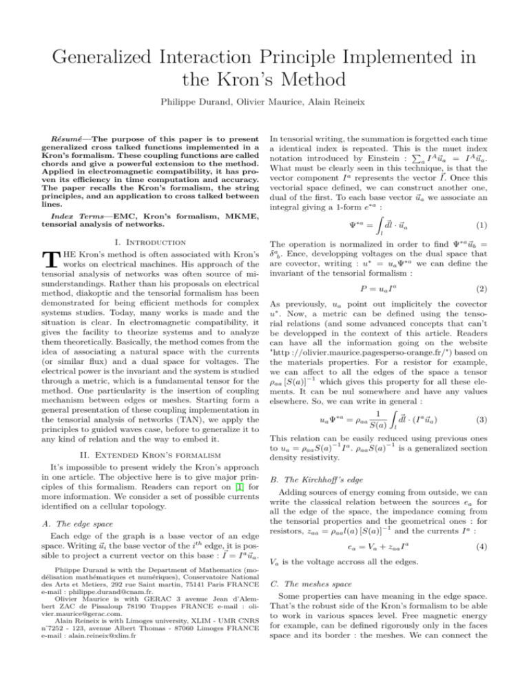
Generalized Interaction Principle Implemented in the Kron’s Method Philippe Durand, Olivier Maurice, Alain Reineix Résumé—The purpose of this paper is to present generalized cross talked functions implemented in a Kron’s formalism. These coupling functions are called chords and give a powerful extension to the method. Applied in electromagnetic compatibility, it has proven its efficiency in time computation and accuracy. The paper recalls the Kron’s formalism, the string principles, and an application to cross talked between lines. Index Terms—EMC, Kron’s formalism, MKME, tensorial analysis of networks. In tensorial writing, the summation is forgetted each time a identical index is repeated. This P is the muet index A notation introduced by Einstein : ua = I A ~ua . aI ~ What must be clearly seen in this technique, is that the ~ Once this vector component I a represents the vector I. vectorial space defined, we can construct another one, dual of the first. To each base vector ~ua we associate an integral giving a 1-form e∗a : Z ∗a ~ · ~ua Ψ = dl (1) l I. Introduction HE Kron’s method is often associated with Kron’s works on electrical machines. His approach of the tensorial analysis of networks was often source of misunderstandings. Rather than his proposals on electrical method, diakoptic and the tensorial formalism has been demonstrated for being efficient methods for complex systems studies. Today, many works is made and the situation is clear. In electromagnetic compatibility, it gives the facility to theorize systems and to analyze them theoretically. Basically, the method comes from the idea of associating a natural space with the currents (or similar flux) and a dual space for voltages. The electrical power is the invariant and the system is studied through a metric, which is a fundamental tensor for the method. One particularity is the insertion of coupling mechanism between edges or meshes. Starting form a general presentation of these coupling implementation in the tensorial analysis of networks (TAN), we apply the principles to guided waves case, before to generalize it to any kind of relation and the way to embed it. T II. Extended Kron’s formalism It’s impossible to present widely the Kron’s approach in one article. The objective here is to give major principles of this formalism. Readers can report on [1] for more information. We consider a set of possible currents identified on a cellular topology. A. The edge space Each edge of the graph is a base vector of an edge space. Writing ~ui the base vector of the ith edge, it is possible to project a current vector on this base : I~ = I a ~ua . Phiippe Durand is with the Department of Mathematics (modélisation mathématiques et numériques), Conservatoire National des Arts et Metiers, 292 rue Saint martin, 75141 Paris FRANCE e-mail : philippe.durand@cnam.fr. Olivier Maurice is with GERAC 3 avenue Jean d’Alembert ZAC de Pissaloup 78190 Trappes FRANCE e-mail : olivier.maurice@gerac.com. Alain Reineix is with Limoges university, XLIM - UMR CNRS n˚7252 - 123, avenue Albert Thomas - 87060 Limoges FRANCE e-mail : alain.reineix@xlim.fr The operation is normalized in order to find Ψ∗a ~ub = δ ab . Ence, developping voltages on the dual space that are covector, writing : u∗ = ua Ψ∗a we can define the invariant of the tensorial formalism : P = ua I a (2) As previously, ua point out implicitely the covector u∗ . Now, a metric can be defined using the tensorial relations (and some advanced concepts that can’t be developped in the context of this article. Readers can have all the information going on the website "http ://olivier.maurice.pagesperso-orange.fr/") based on the materials properties. For a resistor for example, we can affect to all the edges of the space a tensor −1 ρaa [S(a)] which gives this property for all these elements. It can be nul somewhere and have any values elsewhere. So, we can write in general : Z 1 ~ · (I a ~ua ) ua Ψ∗a = ρaa dl (3) S(a) l This relation can be easily reduced using previous ones −1 −1 to ua = ρaa S(a) I a . ρaa S(a) is a generalized section density resistivity. B. The Kirchhoff’s edge Adding sources of energy coming from outside, we can write the classical relation between the sources ea for all the edge of the space, the impedance coming from the tensorial properties and the geometrical ones : for −1 resistors, zaa = ρaa l(a) [S(a)] and the currents I a : ea = Va + zaa I a (4) Va is the voltage accross all the edges. C. The meshes space Some properties can have meaning in the edge space. That’s the robust side of the Kron’s formalism to be able to work in various spaces level. Free magnetic energy for example, can be defined rigorously only in the faces space and its border : the meshes. We can connect the Figure 1. p is the Laplace’s operator. For the moment, we don’t have cross talked betweent he edges. It could be possible, some functions may have been added to translate interactions between them. Making the bilinear transformation we obtain : 0 R1 + C12 p (9) zµν = Lµa zab Lbν = 1 0 C3 p + R4 Simple example edges in meshes using a connectivity : ia = Laβ k β . k β are the meshes currents. Changing the edge currents in the Kirchhoff’s relation we obtain : ea = Va + zaa Laβ k β . Now we can multiply both members by the transposed matrix Lαa to obtain : Lαa ea = Lαa Va + Lαa zaa Laβ k β . We use here classical rules of tensorial calculus. But the product by L is an equivalent operation in cellular topology to a rotationnal applied here on a gradient. So, Lαa Va = 0. The two other products give the electromotive forces in the meshes space (which can include magnetic induction from Faraday’s law) and the impedance in the mesh space. Finally, the whole problem is synthesized in the tensorial equation : eα = zαβ k β (5) In this space we can easily add the inductance of each mesh Sββ , and the mutual ones between meshes Sαβ . The result stills valid due to the tensorial formalism used backside. The invariant stills respected : ua I a = uα Lαa Laα k α = uα k α = P (6) Note that rigorously, k and I are the same object, seen from two different reference frames. That’s only for practical reasons that we change the symbol for the current. III. A simple example We consider two circuits made each of one resistor and one capacitor. The network is shown fig.1. We just need to represent the graph of our topology. Each edge has implicitely its own properties. Edges are oriented and the meshes too, giving the connectivity L : 1 0 1 0 L= (7) 0 1 0 1 We can define the metric in the edge space, i.e. the impedance fonctions of each edge (we meean by impedance the generalized operator giving the relation between a current in an edge and the voltage dopred across). Seeing this metric, the nature of each edge appears clearly. Edges are numbered from 1 to 4, the edge space dimension is 4. For example we describe the impedance tensor (metric) as : R1 0 0 0 0 C1 p 0 0 2 (8) zab = 1 0 0 0 C3 p 0 0 0 R4 Now we can add some inductances values associated with each circuit, coming from their loops : 0 R1 + C12 p + L1 p a b zµν = Lµ zab L ν = 1 0 C3 p + R4 + L2 p (10) And finally, add the interaction through mutual inductance m between the two loops (we don’t care here of the exact formulation of these elements. Our study is abstract and we theorize the problem) : −m12 p R1 + C12 p + L1 p zµν = Lµa zab Lbν = 1 −m21 p C3 p + R4 + L2 p (11) We see that the various steps in the problem construction follow the natural minding of an engineer. That’s a very interesting side of the approach. Another fact is that the mesh space dimension is here only 2, two times lower than the edge one. IV. The simple and generalized interaction process When we have wanted to add the magnetic interaction between the two loops in the previous example, we add both m21 and m12 extra-diagonal components. The mechanical effect of these elements is to create two electromotive force (emf) on each mesh, coming from opposite mesh current. If only loop one has a source of energy, the system of equations obtain form the tensorial one (5) is : e1 = z11 k 1 + z12 k 2 (12) 0 = z21 k 1 + z22 k 2 Writing e2→1 = z12 k 2 and e1→2 = z21 k 1 , the system becomes : e1 − e2→1 = z11 k 1 (13) e1→2 = z22 k 2 But the components ex→y where x and y point out any sources of fields anywhere, connected with currents and can be considered as constructed by any physical process. It means that the extradiagonal components m12 p and m21 p can be replaced by functions of any complexity. That’s the basic ideas of chords. In particular, the chords can take in charge processes coming from the 3D space of free fields. The general schematic is presented figure 2. To illustrate the mechanism, we apply the principle to a simple magnetic moment coupling between the two previous loops. A current in a cellular topology of dimension 1 (T 1 ) create through an operator of integration ∂ o a field source At in a 2 dimension element T 2 . This source radiates on a spherical surface SE by a function φ and reach another cellular topology, transported by a Green function G in R4 domain. The inverse process is realized in the reception circuit to create a local emf. Thisl eads to define an affine interaction. Terms in impedance give the interaction between the two meshes of the extremities of the line : x z12 = ke12 = (Zc − RL ) e− v p x (21) z21 = ke21 = (Zc − R0 ) e− v p Figure 2. But it exists too an added emf coming from the source E, delayed : x E 0 → E Ee− v p (22) Generalized free field process That’s why we call this kind of interaction affine one. VII. Power Chopper Figure 3. Branin’s modelling for a line V. Far field radiation between the two loops The first loop is characterized by its mesh current k 1 and its surface S(1). We can compute the far magnetic field generated by the loop : ~ θ = µ πsinθ k 1 S(1)e− rc p ~uθ B (14) rλ2 (θ is the hight). In the second loop, the emf created by the magnetic field of the previous loop is : ~ ~θ e2 = −S(2) · pB We present now an efficient application of Kron’s method for "electric graphs" (for more details see ref.[2]) : The model is made of two circuits : a first circuit modelling the input of a chopper converter and a second circuit modelling the output of the chopper. On entry, we want to postponed the storage of energy coming from the power supply inside the input capacitor and the discharge in the phase where the top floor of the chopper is opened and the bottom one is closed. On output we want modelling the potential reported on the load (top floor chopper switch closed and bottom one opened ). Figure 4 presents the copper schematic where we can see both switchers k1 and k2, power supply E, input network : Re, Le, Ce and output network : Rs, Ls, Cs and Rdr. (15) Finally, the interaction through the 4D space is given by : r πsinθ e2 ~ (16) = −S(2) · pµ S(1)e− c p ~uθ k1 rλ2 m21 and its symetric m12 is added in the z tensor to take into account this far field 4D space interaction. m21 = Figure 4. Chopper schematic VI. Affine interaction : the Branin’s modelling in the Kron’s formalism Branin’s modelling for lines is based on two equations : x e1 = − V2 − Zci3 e− v p x (17) e2 = V1 + Zc i2 e− v p Fig. 3 shows the configuration used to describe the variables. Using meshes 1 and 2 for both circuits at each extremity of the line, we can write this system under a Kron’s formalism. Firstly we replace V1 and V2 by their expressions : V1 = E − R0 i1 V2 = RL i4 A. Equivalent circuit of our system Figure 5 shows the equivalent circuit of our system with the voltage node pair source and the controlled current source. Our LRC modelling is separated into two networks such that each one is controlled by the other. The second network is powered by the voltage Vdc(t) reported from the first network, and the load current of the second network is is injected in the first network depending on the command law. (18) So : x x −e1 = RL i4 e− v p − Zc i3 e− v p x x x e2 = Ee− v p − R0 i1 e− v p + Zc i2 e− v p (19) Making the transformation to use the meshes space, we obtain : x E − e1 = (RL − Zc ) e− v p k 2 x x (20) Ee− v p + e2 = (Zc − R0 ) e− v p k 1 Figure 5. Equivalent schematic for the chopper The second network includes a generator E2 , given by : E2 = V dc ∗ f sw. B. Topology for the system The visible elements in the graph given Figure 5 are the topological following character : – 4 physical nodes n1,..,n4 (→ N = 4) – 5 branches b1,..,b5 (→ B = 5) – 3 meshes m1,m2,m3 (→ M = 3) – 2 networks R1, R2 (→ R = 2) – 2 nodes pair (→ P = 2) Figure 6. Elements of the chosen topology VIII. Conclusion The generalized interaction terms under the tensorial analysis of networks invented by Kron in 1939 allows to take into account many kind of coupling. Various applications was made using these principles in information[2], guided waves and cavities[3], power choppers[4], etc. Each time it gives very efficient and optimized modelling giving fast and accurate results. Next step could be to apply the approach for numerical schematic. It allows to mix quite easily integral, PEEC and GTD in a common FEM for a numerical tool in Maxwell field computation. But more than anything, the global technique gives a very powerful tool to analyze theoretically the problems of engineers, even in non linear cases[5]. Références [1] O. Maurice, La compatibilité électromagnétique des systèmes complexes, Paris, France : Hermès Sciences, 2007. [2] G. Hubert and O. Maurice, “Combined Effects Induced by Electromagnetic Pulses and Single Event Effect on Electronics,” in EMCCOMPO09 : electromagnetic compatibility of components symposium 2009. [3] O. Maurice, A. Reineix, P. Durand, F. Dubois, ‘Ãn Mathematical Definitions of Chords between Networks," in EUROEM 2012 Symposium on electromagnetism, Toulouse France, 2012. [4] P. Durand,F. Boussandel, O. Maurice, “Power Chopper Modelling Using the Kron’s Method," in Proceeding of the IASTED International Conference Engineering and Applied Science (EAS 2012). Colombo, Sri Lanka, 2012. [5] K. Kondo and al., “emoirs of the Unifying Study of the Basic Problems in Engineering Sciences by Means of Geometry," in University of Tokyo 1955, published by Gakujutsu Bunken Fukyu-Kai.
