Interleaving Thinned Sum and Difference Linear Arrays
advertisement
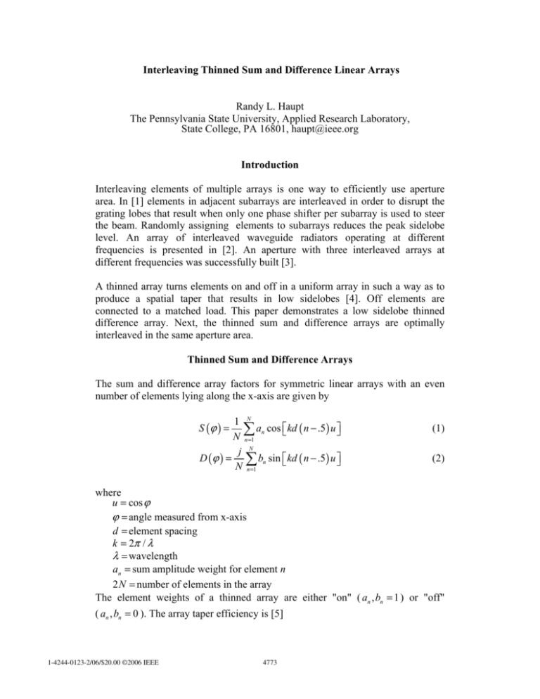
Interleaving Thinned Sum and Difference Linear Arrays Randy L. Haupt The Pennsylvania State University, Applied Research Laboratory, State College, PA 16801, haupt@ieee.org Introduction Interleaving elements of multiple arrays is one way to efficiently use aperture area. In [1] elements in adjacent subarrays are interleaved in order to disrupt the grating lobes that result when only one phase shifter per subarray is used to steer the beam. Randomly assigning elements to subarrays reduces the peak sidelobe level. An array of interleaved waveguide radiators operating at different frequencies is presented in [2]. An aperture with three interleaved arrays at different frequencies was successfully built [3]. A thinned array turns elements on and off in a uniform array in such a way as to produce a spatial taper that results in low sidelobes [4]. Off elements are connected to a matched load. This paper demonstrates a low sidelobe thinned difference array. Next, the thinned sum and difference arrays are optimally interleaved in the same aperture area. Thinned Sum and Difference Arrays The sum and difference array factors for symmetric linear arrays with an even number of elements lying along the x-axis are given by 1 N ∑ an cos ⎡⎣kd ( n − .5) u ⎤⎦ N n =1 j N D (ϕ ) = ∑ bn sin ⎡⎣ kd ( n − .5 ) u ⎤⎦ N n =1 S (ϕ ) = (1) (2) where u = cos ϕ ϕ = angle measured from x-axis d = element spacing k = 2π / λ λ = wavelength an = sum amplitude weight for element n 2 N = number of elements in the array The element weights of a thinned array are either "on" ( an , bn = 1 ) or "off" ( an , bn = 0 ). The array taper efficiency is [5] 1-4244-0123-2/06/$20.00 ©2006 IEEE 4773 η ar = number of elements in the array turned on total number of elements in the array (3) Examples of array factors for a thinned 102 element sum and difference arrays with d = 0.5λ and bN = 1 are shown in Figure 1 and Figure 2. The thinning approach is similar to that in [6]. The thinned sum array has the highest density of elements turned on in the center, while the thinned difference array has few elements turned on in the center. Both arrays have less "on" elements near the edges. These observations lead to the possibility of using the elements turned "off" by the thinned sum array for the thinned difference array. Using the "off" elements from the array in Figure 1 as elements in a difference array does not result in an acceptable difference pattern. Assume that the difference pattern consists of the elements turned off in the sum pattern or bn = 1 − an . Using a GA to find the thinning arrangement that results in the minimum maximum sidelobe level for both array factors results in an array having the patterns shown in Figure 3 and Figure 4. The patterns are normalized to their respective peaks. The peak sidelobe level of the sum pattern is 12.68 dB below its main beam, and the peak sidelobe level of the difference pattern is 12.5 dB below its main beam. The sum array has η ar = 0.48 and the difference array has η ar = 0.52 . The entire aperture is 100% efficient, so optimum use is made of the available space. Conclusions It is possible to interleave a thinned sum array with a thinned difference array to make efficient use of an existing aperture. The GA moderates the sidelobe levels of both arrays while devoting approximately half the elements to each array. References: [1] [2] [3] [4] [5] [6] J. Stangel and J. Punturieri, "Random subarray techniques in electronic scan antenna design," IEEE AP-S Symp., Vol. 10 , Dec 1972, pp. 17 – 20. J. Hsiao, "Analysis of interleaved arrays of waveguide elements," IEEE AP-S Trans., Vol. 19, No. 6 , Nov 1971, pp.729 – 735. J. Boyns and J. Provencher, "Experimental results of a multifrequency array antenna," IEEE AP-S Trans., Vol. 20, No. 1, Nov 1972, pp.106-107. R. Willey, "Space tapering of linear and planar arrays," IEEE AP-S Trans., vol. AP-10, 1962, pp. 369-377. R.J. Mailloux, Phased Array Antenna Handbook, Boston, MA: Artech House, 1994. R.L. Haupt, "Thinned arrays using genetic algorithms," IEEE AP-S Trans., vol. AP-42, 1994, pp. 993-999. 4774 Figure 1. Thinned sum array. Figure 2. Thinned difference array. 4775 Figure 3. Sum array factor due to interleaved thinned sum and difference arrays. Figure 4. Difference array factor due to interleaved thinned sum and difference arrays. 4776

