Question 1 - UniMAP Portal
advertisement
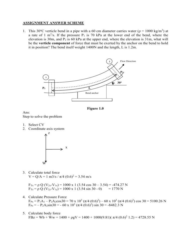
ASSIGNMENT ANSWER SCHEME 1. This 30oC verticle bend in a pipe with a 60 cm diameter carries water (ρ = 1000 kg/m3) at a rate of 1 m3/s. If the pressure P1 is 70 kPa at the lower end of the bend, where the elevation is 30m, and P2 is 60 kPa at the upper end, where the elevation is 31m, what will be the verticle component of force that must be exerted by the anchor on the bend to hold it in position? The bend itself weight 1400N and the length, L is 1.2m. 2 Flow Direction P2 1 30o P1 L Bend anchor Figure 1.0 Ans: Step to solve the problem 1. Select CV 2. Coordinate axis system z x W 3. Calculate total force V = Q/A = 1 m3/s / π/4 (0.6)2 = 3.54 m/s FTx = ρ Q (V2x-V1x) = 1000 x 1 (3.54 cos 30 – 3.54) = -474.27 N FTz = ρ Q (V2y-V1y) = 1000 x 1 (3.54 sin 30 - 0) = 1770 N 4. Calculate Pressure Force FPx = P1A1 – P2A2cos30 = 70 x 103 (π/4 (0.6)2) – 60 x 103 (π/4 (0.6)2) cos 30 = 5100.26 N FPz = – P2A2sin30 = - 60 x 103 (π/4 (0.6)2) sin 30 = -8482.3 N 5. Calculate body force FBz = Wb + Ww = 1400 + ρgV = 1400 + 1000(9.81)( π/4 (0.6)2 1.2) = 4728.55 N 6. Calculate resultant force FRx = FTx – FPx – FBx = -474.27 -5100.26-0 = -5574.5 N FRz = FTz – FPz – FBz = 1770 + 8482.3 –(-4728.55 ) = 14980 N (Answer – the verticle component of force need to hold bend in position) 2. A liquid of density r and viscosity m flows by gravity through a hole of diameter d in the bottom of a tank of diameter D (Fig. 2.0). At the start of the experiment, the liquid surface is at height h above the bottom of the tank, as sketched. The liquid exits the tank as a jet with average velocity V straight down as also sketched. Using dimensional analysis, generate a dimensionless relationship for V as a function of the other parameters in the problem. Identify any established nondimensional parameters that appear in your result. (Hint: There are three length scales in this problem. For consistency, choose h as your length scale.) Figure 2.0 Answer: Step 1: List all the variable and count n V = f( D,ρ,μ, d, h , g) n=7 Step 2: List the variable dimension and count m involve. Calculate the k (π group) V = LT-1 D=L ρ = ML-3 μ = ML-1T-1 d=L h=L g = LT-2 m=3 Step 3 : Calculate the k (π group) k = n – m = 4 π group Step 4 : Choose repeating parameter ρ, h , g Step 5 : Generate the π group D d , π3 = , π4 = 3/ 2 h h h g gh Step 6 : Check all the π group and write the final fucntional relationship in the form π1 = V , π2 = π1 = f(π1, π2, π3,...) π1 = f( D d , 3/ 2 , ) g h gh h h V , 3. Oil at 26.67°C (ρ = 909.8 kg/m3 and μ = 0.0413 N.s/m2) is flowing steadily in a 1.25cm diameter, 36.5m long pipe. During the flow, the pressure at the pipe inlet and exit is measured to be 827 kPa and 96 kPa, respectively. Determine the flow rate of oil through the pipe assuming the pipe is (a) horizontal, (b) inclined 20° upward, and (c) inclined 20° downward. Answer: PD 4 (827 x10 3 96 x10 3 ) (0.0125) 4 = = 2.906 x 10⁻⁴ m3/s = 0.29 L/s 128L 128(0.0413x36.5) 4 (P gL sin )D ((827 x10 3 96 x10 3 ) 909.8x9.81x36.5 sin 20) (0.0125) 4 b) Q= = 128L 128(0.0413x36.5) = 2.46 x 10⁻⁴ m3/s = 0.25 L/s (P gL sin )D 4 ((827 x10 3 96 x10 3 ) 909.8x9.81x36.5 sin 20) (0.0125) 4 c) Q = 128L 128(0.0413x36.5) -4 3 = 3.234 x 10 m /s = 0.32 L/s a) Q = vA = 4. Water at 15°C (ρ = 999.1 kg/m3 and μ = 1.138 x 10⁻³ kg/m.s) is flowing steadily in a 30m long and 4cm diameter horizontal pipe made of stainless steel at a rate of 8 L/s. Determine (a) the pressure drop, (b) the head loss, and (c) the pumping power requirement to overcome this pressure drop. Figure 3.0 Answer: V = Q/A = 8 x 10⁻³ m3/s / π/4 (0.04)2 = 6.37 m/s Re = Vd / = 999.1 x 6.37 x 0.04/1.138 x 10-3 = 2.24 x 10⁵ therefore the flow is turbulent. Find the f from Moody Chart, Є = 0.002mm, Relative roughness = Є/d = 0.002 x 10⁻³/0.04 = 5 x 10⁻⁵ , so f = 0.0165 a) ∆P = ( f L v2 30 6.37 2 )( g ) 0.0165 999.1x9.81 251kPa D 2g 0.04 2(9.81) P 251x10 3 25.6m g 999.1(9.81) c) W pump = Q∆P = 251x 103 Pa x 8 x 10-3 m3/s = 2008 Watt = 2 kW b) Head loss, hL = 5. A flow nozzle equipped with a differential pressure gage is used to measure the flow rate of water at 10°C (ρ = 999.7 kg/m3 and μ =1.307 x 10⁻³ kg/m · s) through a 3- cm-diameter horizontal pipe. The nozzle exit diameter is 1.5 cm, and the measured pressure drop is 3 kPa. Determine the volume flow rate of water, the average velocity through the pipe, and the head loss. Figure 4.0 1.5cm 0.5 3.0cm Q AoCd 2P 2(3x10 3 2 ( 0 . 03 ) x 0 . 96 x 4.30 x10 4 m 3 / s (1 4 ) 4 999.7(1 0.5 4 ) Q 4.30 x10 4 m 3 / s v 0.61m / s A / 4(0.03) 2 hL P 3x10 3 0.31m g 999.7(9.81) 6. The resultant of the pressure and wall shear forces acting on the body (Figure 5.0) is measured to be 700N, making 35o with the direction of flow. Determine the drag and lift forces acting on the body. v θ = 35o FD FR cos 700 cos 35 573.4 N Figure 5.0 FL FR sin 700 sin 35 401.5 N 7. Wind loading is a primary consideration in the design of the supporting mechanisms in billboards, as evidenced by many billboards being knocked down during high winds. Determine the wind force acting on a 2.4m high, 6m wide billboard due to 140 km/h winds in the normal direction when the atmospheric condition are 98kPa and 4.5oC. (ρ = 1.237 kg/m3) Answer: A = HW = 2.4 x 6 =14.4 m2 W/H= 2.4/6=0.4, CD = 2.35 (Table) v 2 1.237 x38.89 2 FD C D A 2.35 x14.4 x 31.7kN 2 2 8. As shown, wind is blowing on a 208 litre drum. Estimate the wind speed need to tip the drum over. The mass of drum is 21.8 kg, the diameter is 0.571m and the height is 0.876m. D v H Figure 6.0 Answer: 208 L 0.208m 3 m 21.8kg 104.8kg / m 3 3 0.208m W= g 104.8 x9.81x0.208 213.84 N WD 213.84 x0.571 FD 139.39 N H 0.876 A HD 0.5m 2 H / D 1.53, C D 0.65 139.39 0.65 x0.5 x 104.8 xv2 2 V= 2.86 m/s 9. The drag coefficient of the vehicle increases when its windows are rolled down or its sunroof is opened. A sport car has a frontal area of 1.6 m2 and a drag coefficient of 0.32 when the windows and sunroof is closed. The drag coefficient increases to 0.41 when the sunroof is open. Determine the additional power consumption when the sunroof is opened at a) 55 km/h and b)110km/h. Take the density of air to 1.2 kg/m3. v 2 1.2 x15.28 2 20.2 N 2 2 W 20.2x15.28 308.7Watt = 0.31 kW v 2 1.2 x30.56 2 (0.41 0.32) x1.6 x 80.7 N b) FD C D A 2 2 W 80.7 x30.56 2466.2Watt = 2.4 kW a) ∆ FD C D A (0.41 0.32) x1.6 x

