Name:
advertisement
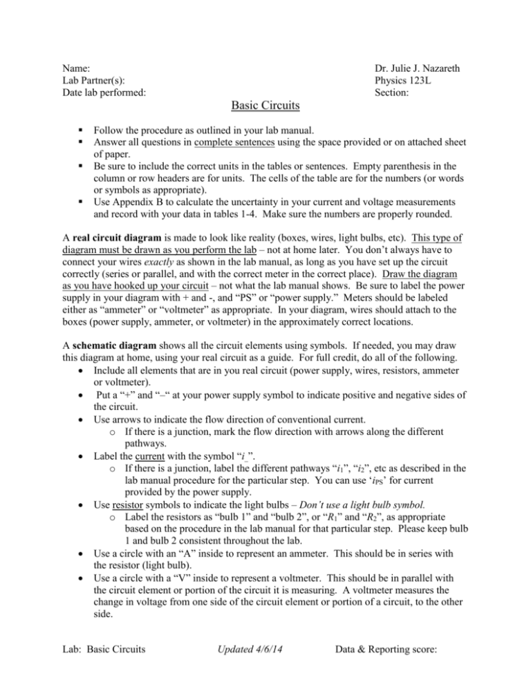
Name: Lab Partner(s): Date lab performed: Dr. Julie J. Nazareth Physics 123L Section: Basic Circuits Follow the procedure as outlined in your lab manual. Answer all questions in complete sentences using the space provided or on attached sheet of paper. Be sure to include the correct units in the tables or sentences. Empty parenthesis in the column or row headers are for units. The cells of the table are for the numbers (or words or symbols as appropriate). Use Appendix B to calculate the uncertainty in your current and voltage measurements and record with your data in tables 1-4. Make sure the numbers are properly rounded. A real circuit diagram is made to look like reality (boxes, wires, light bulbs, etc). This type of diagram must be drawn as you perform the lab – not at home later. You don’t always have to connect your wires exactly as shown in the lab manual, as long as you have set up the circuit correctly (series or parallel, and with the correct meter in the correct place). Draw the diagram as you have hooked up your circuit – not what the lab manual shows. Be sure to label the power supply in your diagram with + and -, and “PS” or “power supply.” Meters should be labeled either as “ammeter” or “voltmeter” as appropriate. In your diagram, wires should attach to the boxes (power supply, ammeter, or voltmeter) in the approximately correct locations. A schematic diagram shows all the circuit elements using symbols. If needed, you may draw this diagram at home, using your real circuit as a guide. For full credit, do all of the following. Include all elements that are in you real circuit (power supply, wires, resistors, ammeter or voltmeter). Put a “+” and “–“ at your power supply symbol to indicate positive and negative sides of the circuit. Use arrows to indicate the flow direction of conventional current. o If there is a junction, mark the flow direction with arrows along the different pathways. Label the current with the symbol “i_”. o If there is a junction, label the different pathways “i1”, “i2”, etc as described in the lab manual procedure for the particular step. You can use ‘iPS’ for current provided by the power supply. Use resistor symbols to indicate the light bulbs – Don’t use a light bulb symbol. o Label the resistors as “bulb 1” and “bulb 2”, or “R1” and “R2”, as appropriate based on the procedure in the lab manual for that particular step. Please keep bulb 1 and bulb 2 consistent throughout the lab. Use a circle with an “A” inside to represent an ammeter. This should be in series with the resistor (light bulb). Use a circle with a “V” inside to represent a voltmeter. This should be in parallel with the circuit element or portion of the circuit it is measuring. A voltmeter measures the change in voltage from one side of the circuit element or portion of a circuit, to the other side. Lab: Basic Circuits Updated 4/6/14 Data & Reporting score: Part A: Series Circuit Page 3: Draw both a schematic diagram and a sketch of the real circuit for the series circuit. Schematic diagram Real circuit Question 1: What happens when you unscrew one of the light bulbs from its socket? Be specific and explain why it happened. Connecting an ammeter: For all of the ammeter readings, make sure that you DO NOT change the voltage setting on the power supply. Simply turn off the power supply to connect or reconnect the ammeter. Page 4: Connect the ammeter in series BEFORE the first bulb to measure the current going into the first bulb, I1. Then, connect the ammeter between the two bulbs to measure the current going into the second bulb, I2. Table 1: Current measurements for series circuit Current (bulb 1), Current (bulb 2), I1 ( ) I2 ( ) ± ± Relationship between I1 and I2 Connecting a voltmeter: For all of the voltmeter readings, make sure that you DO NOT change the voltage setting on the power supply. Simply turn off the power supply to connect or reconnect the voltmeter. Page 5: Connect the voltmeter in parallel with the first bulb to measure the voltage across (from one side of the bulb to the other) the one light bulb, V1. Next connect the voltmeter in parallel with the second bulb only to measure the voltage, V2. Then, connect the voltmeter across both bulbs to measure the voltage across the combination of light bulbs, V. Table 2: Voltage measurements for series circuit Voltage (bulb 1), Voltage (bulb 2), Voltage (combination), V1 ( ) V2 ( ) V( ) Lab: Basic Circuits Updated 4/6/14 Relationship between V, V1 and V2 ± ± ± Part B: Parallel Circuit Page 6: Connect your light bulbs and power supply in a parallel circuit Question 2: What happens when you unscrew one of the light bulbs from its socket? Be specific and explain why it happened. For all of the following, make sure that you DO NOT change the voltage setting on the power supply. Turn off the power supply each time BEFORE you reconnect the circuit. Page 7: Connect the ammeter in series between power supply and only one of the bulbs. Draw a schematic drawing to show the connections. Measure the current, I1. Reconnect the ammeter so it reads current through the other bulb only, I2. Reconnect the ammeter so it reads current through the combination of both bulbs, I. Draw a schematic diagram to show the ammeter reading current going into both bulbs. Schematic diagram (measuring one bulb) Schematic diagram (combination of bulbs) Table 3: Current measurements for a parallel circuit Current (bulb 1), Current (bulb 2), Current (combination), I1 ( ) I2 ( ) I( ) ± ± ± Relationship between I, I1, and I2 Page 8: Connect the voltmeter to measure the voltage, V, across the combination of the two bulbs. Draw a schematic diagram for this set-up. Next, connect the voltmeter across just one of the bulbs and measure the voltage, V1. Draw a schematic diagram for this set-up. Schematic diagram (combination of bulbs) Schematic diagram (one bulb only) Lab: Basic Circuits Updated 4/6/14 Table 4: Voltage measurements for parallel circuit Voltage (combination), Voltage (one bulb), V( ) V1 ( ) ± ± Relationship between V and V1 Calculations: In the space below or on an attached sheet of paper, show the calculation of the uncertainty in the electronic meter for all of the current and voltage values recorded in tables 1thru 4. Series circuit bulb 1 current uncertainty: Series circuit bulb 2 current uncertainty: Series circuit bulb 1 voltage uncertainty: Series circuit bulb 2 voltage uncertainty: Series circuit combo voltage uncertainty: Parallel circuit bulb 1 current uncertainty: Parallel circuit bulb 2 current uncertainty: Parallel circuit combo current uncertainty: Parallel circuit one bulb voltage uncertainty: Parallel circuit combo voltage uncertainty: Question 3 (Instead of summary): What was the goal of, reason for, or purpose of the Basic Circuits lab? (Write your answer as if you were writing the introductory sentence to your summary/conclusion paragraph. Do NOT plagiarize the lab manual or fellow students.) Lab: Basic Circuits Updated 4/6/14
