CMOS Transmission Gates:
advertisement
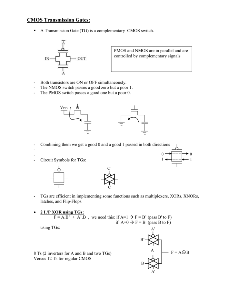
CMOS Transmission Gates: A Transmission Gate (TG) is a complementary CMOS switch. PMOS and NMOS are in parallel and are controlled by complementary signals - Both transistors are ON or OFF simultaneously. The NMOS switch passes a good zero but a poor 1. The PMOS switch passes a good one but a poor 0. VDD - Combining them we get a good 0 and a good 1 passed in both directions 0 1 Circuit Symbols for TGs: 0 1 C’ C - TGs are efficient in implementing some functions such as multiplexers, XORs, XNORs, latches, and Flip-Flops. 2 I./P XOR using TGs: F = A.B’ + A’.B , we need this: if A=1 F = B’ (pass B' to F) if A=0 F = B (pass B to F) using TGs: A’ B’ A 8 Ts (2 inverters for A and B and two TGs) Versus 12 Ts for regular CMOS B A' F=A+B 2 I/P XNOR F = A.B + A’B’ if A=1 pass B to F if A=0 pass B’ to F A B’ A’ B A General Logic using TGs: AOI 22: F = (AB + CD)’ if A=1 F = (B+CD)’ Then if C=1 F= (B+D)’ … and so on…. B’ 0 C’ B B A’ 24 Ts versus 8 T for regular CMOS TGs are very inefficient for regular functions C C D’ B’ A A B' C’ C’ A’ D’ C C 1 C’ S’ 2-1 mux using TGs F = S’.D0 + S.D1 S 0 1 Y D0 D1 D1 D0 S S Y D1 D0 S S’ Y 4-1 Mux in TGs: Y = S1’.S0’.D0 + S1’.S0.D1 + S1.S0’.D2 + S1.S0.D3 S0 S1 D0 D1 D2 D3 D0 S0’ S0’ S1’ S1 S0 S0 S'1 S'1 S0’ S'0 S1 S'1 S0 S1 Y S0 S 1 D1 S1 0 0 1 1 Y D2 S0 0 1 0 1 Y D0 D1 D2 D3 20 Ts D3 Another way is to use 3 of 2-1 Muxs: S0 D0 D0 S0' S0’ D1 S1 Y S0 D1 D2 S0 S0 S1' S1’ D2 S1 D3 S0 S0' S0’ D3 S0 S1 We can use the same concept to make 3,4 or more I/Ps XORs 4 I/P XOR: A' B A A B' A' F=A+B+C+D C' D D' C C C' F = A.B’.C’.D’ + A’.B.C’.D’ + A’.B’.C.D’ + A.B.C.D’ + A.B.C.D’ + A.B.C’.D + A.B’.C.D In regular CMOS: 4 inverters + 64T = 72 T Warning: TGs can not be connected in series for more than 3 levels If you need more than that, use CMOS inverters in between as buffers:


