Laboratory Manual to the Course
advertisement

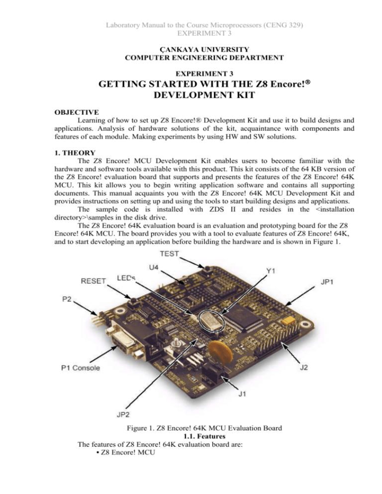
Laboratory Manual to the Course Microprocessors (CENG 329) EXPERIMENT 3 ÇANKAYA UNIVERSITY COMPUTER ENGINEERING DEPARTMENT EXPERIMENT 3 GETTING STARTED WITH THE Z8 Encore! DEVELOPMENT KIT OBJECTIVE Learning of how to set up Z8 Encore!® Development Kit and use it to build designs and applications. Analysis of hardware solutions of the kit, acquaintance with components and features of each module. Making experiments by using HW and SW solutions. 1. THEORY The Z8 Encore! MCU Development Kit enables users to become familiar with the hardware and software tools available with this product. This kit consists of the 64 KB version of the Z8 Encore! evaluation board that supports and presents the features of the Z8 Encore! 64K MCU. This kit allows you to begin writing application software and contains all supporting documents. This manual acquaints you with the Z8 Encore! 64K MCU Development Kit and provides instructions on setting up and using the tools to start building designs and applications. The sample code is installed with ZDS II and resides in the <installation directory>\samples in the disk drive. The Z8 Encore! 64K evaluation board is an evaluation and prototyping board for the Z8 Encore! 64K MCU. The board provides you with a tool to evaluate features of Z8 Encore! 64K, and to start developing an application before building the hardware and is shown in Figure 1. Figure 1. Z8 Encore! 64K MCU Evaluation Board 1.1. Features The features of Z8 Encore! 64K evaluation board are: • Z8 Encore! MCU Laboratory Manual to the Course Microprocessors (CENG 329) EXPERIMENT 3 • 3 LEDs • RS-232 interface • IrDA transceiver (U4) • Two pushbuttons, RESET and TEST • 5 V DC power connector • On-Chip Debugger interface • Crystal Oscillator at 18.432 MHz • Header for ADC input • Prototyping area • External interface connectors JP1 and JP2 • 2.7 V to 3.6 V operating voltage with 5 V-tolerant inputs. 1.2. MCU The Z8 Encore! 64K MCU is member of a family of ZiLOG microcontroller products based upon the 8-bit eZ8 core CPU. The Flash in-circuit programming capability allows for faster development time and program changes in the field. The eZ8 core CPU is upward compatible with existing Z8® instructions. The rich peripheral set of the Z8F642 makes it suitable for a variety of applications including motor control, security systems, home appliances, personal electronic devices, and sensors. The evaluation board contains circuitry to support and present all the features of the Z8F642. The main features of the Z8F642 are: • eZ8 core CPU • 64 KB Flash memory with in-circuit programming capability • 4 KB register RAM • 5-channel, 10-bit analog-to-digital converter (ADC) • Full-duplex UART • I2C interface (Master Mode only) • Serial Peripheral Interface (SPI) • Infrared Data Association (IrDA)-compliant infrared encoder/decoder • Two 16-bit timers with capture, compare, and PWM capability • Watchdog Timer (WDT) with internal RC oscillator • Eleven or nineteen I/O pins • Programmable priority interrupts • On-Chip Debugger (OCD) • Voltage Brownout Protection (VBO) • Power-on Reset (POR) • 2.7 to 3.6 V operating voltage with 5 V-tolerant inputs • Operating temperatures: 20 °C ±10 °C For further information on the Z8 Encore! family of devices, refer to the product specification (PS0199) available for download at www.zilog.com. 1.3. UART with IrDA Endec The Z8 Encore! 8K/4K contains a fully-functional, high-performance UART with Infrared Encoder/Decoder (ENDEC), component U6. The Infrared Endec is integrated with an on-chip UART allowing easy communication between the Z8 Encore! 8K/4K and IrDA transceivers. Infrared communication provides secure, reliable, low-cost, point-to-point communication between PCs, PDAs, cell phones, printers and other infrared enabled devices. 1.4. Crystal Oscillator The evaluation board ships with an 18.432 MHz Crystal Oscillator (Y1). If you want to change the change the Crystal Oscillator you are required to change the Clock Frequency in for ZDS II. The frequency settings can be found at Project → Settings → Debugger → ZDB: Laboratory Manual to the Course Microprocessors (CENG 329) EXPERIMENT 3 Configure ZDB Driver: Clock Frequency. Refer to the Z8Encore! Product Specification for supported frequencies. 1.5. Power and Communication Interfaces Table 1 provides jumper information concerning the shunt status, functions, devices and defaults affected of jumpers JP3 and JP4. Table 1. Jumpers JP3 and JP4 Jumper Status Device Affected Status Default JP3** OUT* IrDA interface Enable JP3 IN IrDA interface Disable X JP4 OUT RS-232 interface Enable X JP4 IN RS-232 interface Disable 1.6. External Interface Headers JP1 and JP2 The external interface headers, JP1 and JP2 contain no connectors when the board is shipped. You can insert 0.1" space connectors of choice. 1.7. Setting up the Evaluation Board The PC communicates with the Z8 Encore! 64K Evaluation Board using the serial port of the PC. A Z8 Encore! Smart Cable converts the RS-232 signals into the 3.3V bidirectional opendrain signal needed to communicate with the on-chip debugger of the eZ8. Caution: Installing the ZDS II Z8 Encore! Software always use a grounding strap to prevent damage resulting from electro-static discharge (ESD). 1. Connect the serial port of the PC to the Z8 Encore! Smart Cable DB-9 female connector. 2. Connect the Z8 Encore! Smart Cable to the Z8 Encore! 64K MCU evaluation board pin header P2. 3. Connect the power supply to the evaluation board at J1, then to an electrical outlet (Figure 2). Figure 2. Evaluation Board External Connections 1.8. Getting Started Using ZDS II Follow the below procedure to open and use the ledBlink.pro sample project: Laboratory Manual to the Course Microprocessors (CENG 329) EXPERIMENT 3 Note: These procedures refer the ledBlink.zdsproj file located in c:\Program Files\ZiLOG\ZDSII_Z8Encore_<version_number>\Samples\Z8xxxx_ ledBlink\src, where <version_number> is the ZDS II version number and Z8xxxx is the CPU family. For example: c:\Program Files\ZiLOG\ZDSII_Z8Encore_4.10.0\Samples\ Z8F64_ledBlink\src 1. Connect and supply power to the development board. 2. Run the ZDSII software. By default, the ZDSII program is located in the Start menu in the below path: Programs → ZiLOG ZDSII Z8 Encore! <version_number> → ZDSII Z8 Encore! <version_number> 3. Select Open Project from the File menu. The Open Project dialog box appears. Note: The sample used in the following steps is in ‘C’ programming language. An assembler version of the ledBlink sample is located in the path below: Z8xxxx_ledBlink_asm\src 4. Browse to the Samples folder for the ledBlink.zdsproj file, located by default in: c:\Program Files\ZiLOG\ZDSII_Z8Encore_<version_number>\Samples\ Z8xxxx_ledBlink\src 5. Select the ledblink.zdsproj file and click Open. The initial ZDSII program screen is displayed. 6. If you want to view the project source files, double-click on the Project Files folder on left side of the IDE interface. Double-click on an individual file to open that file in the ZDS II file editor. Rebuild All Icon 7. Click the Rebuild All icon to build the project. Wait for the build to be complete. Reset Icon 8. Click the Reset icon to connect and download the code to the development board. Go Icon 9. Click Go to start the program. The screen changes are illustrated in Figure 3 on page 9. 10. The three LEDs on the development board start blinking in sequence. If the LEDs do not blink, start over from Step 2. 11. Press the TEST pushbutton to change the sequence of the LEDs to blink in the opposite direction. Laboratory Manual to the Course Microprocessors (CENG 329) EXPERIMENT 3 Figure 3. ZDS II Active Screen 10. The three LEDs on the development board start blinking in sequence. If the LEDs do not blink, start over from Step 2 on page 7. 11. Press the TEST pushbutton to change the sequence of the LEDs to blink in the opposite direction. 2. PRELIMINARY WORK 2.1. Carefully analyze theory of Evaluation Kit to manipulate procedures of Z8 programming. Prepare individual plan to realize analyses of how operate Evaluation Kit together with developing system, executing programs written in codes of Z8. 2.2. Design program to calculate “running sum” equation, summing unsigned integer variable i: 10 K i i 1 a). In codes of ANSI C. b). Using ASSEMBLER of microprocessor Z8 Encore! Note: You need to make modifications in your project settings in order to test your assembly program using the evaluation board as follows: 1. In “Linker” tab, select the category as “Input”, select “Included In Project”. 2. Uncheck “Use C Runtime Library”. While you are working on the evaluation board, you may need to use some breakpoints and infinite loops to observe the status of registers or variables. Laboratory Manual to the Course Microprocessors (CENG 329) EXPERIMENT 3 3. EXPERIMENTAL WORK 3.1. Following instructions of the manual step-by-step explore program ledblink, described in section 1.8. Note: Do NOT forget to check your CPU family on the evaluation board to choose proper version of the program ledblink. 3.2. Process all steps to execute both prepared programs: a). Simulating Z8 Encore! in personal computer. b). Realizing in development board on Z8 Encore! 4. RESULTS AND CONCLUSIONS 4.1. Explain obtained results, give your explanations of processes during experiments. 5. SELF TEST QUESTIONS 5.1. Simulator is: a). External hardware solution. b). Special software. 5.2. Emulator is: a). External hardware solution. b). Special program. 5.3. What is the difference between unsigned integer and positive integer? 5.4. What is meant by the term set when applied to a control bit? 5.5. What is meant by the term clear when applied to a control bit? 5.6. What effect does the instruction NOP have? 5.7. Why are timing cycles important for real-time programming? 5.8. Why do we express execution time in cycles rather than in divisions of seconds? REFERENCES 1. ZiLOG Developer Studio II – Z8 Encore!, User Manual, UM013026 – 0105 2. High Performance 8-Bit Microcontrollers, PB012403-0304, Z8 Encore!® 64K Series, Product Brief. 3. Product Specification, High Performance 8-Bit Microcontrollers, Z8 Encore!® 64K Series, PS019908-0404. 4. Z8F64200100KIT Z8 Encore!® 64K Series MCU, Development Kit, User Manual UM015103-1203. 5. Z8 Encore!® Development Kits, Quick Start Guide QS002806-0906


