ieee-nano-2005
advertisement
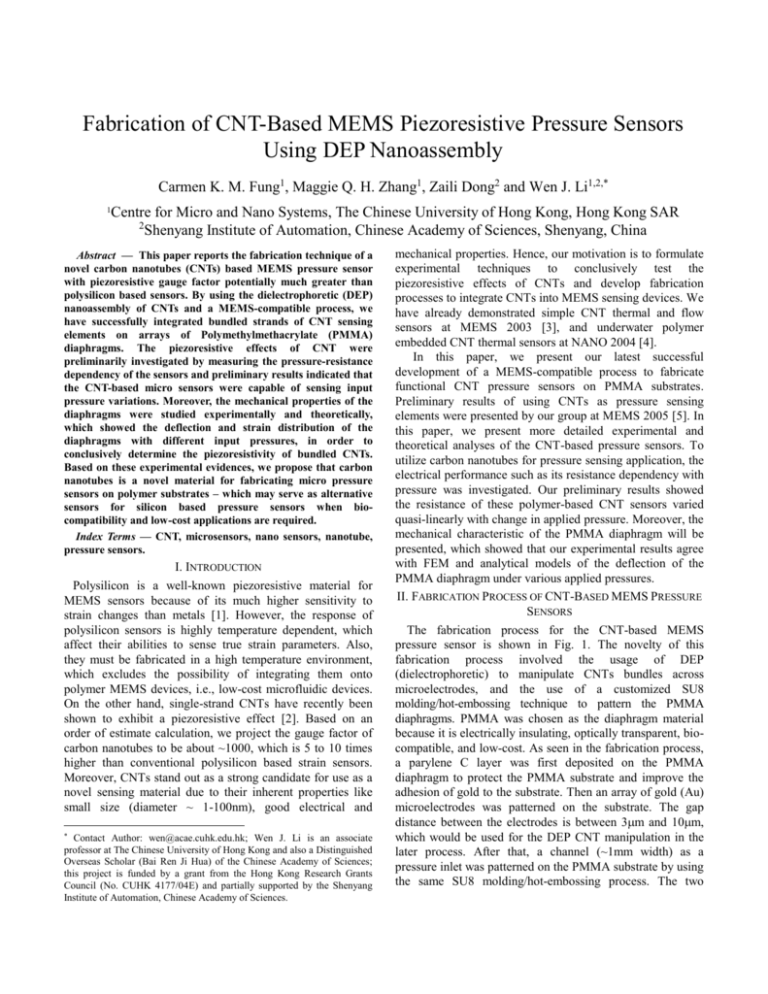
Fabrication of CNT-Based MEMS Piezoresistive Pressure Sensors Using DEP Nanoassembly Carmen K. M. Fung1, Maggie Q. H. Zhang1, Zaili Dong2 and Wen J. Li1,2,* 1 Centre for Micro and Nano Systems, The Chinese University of Hong Kong, Hong Kong SAR 2 Shenyang Institute of Automation, Chinese Academy of Sciences, Shenyang, China — This paper reports the fabrication technique of a novel carbon nanotubes (CNTs) based MEMS pressure sensor with piezoresistive gauge factor potentially much greater than polysilicon based sensors. By using the dielectrophoretic (DEP) nanoassembly of CNTs and a MEMS-compatible process, we have successfully integrated bundled strands of CNT sensing elements on arrays of Polymethylmethacrylate (PMMA) diaphragms. The piezoresistive effects of CNT were preliminarily investigated by measuring the pressure-resistance dependency of the sensors and preliminary results indicated that the CNT-based micro sensors were capable of sensing input pressure variations. Moreover, the mechanical properties of the diaphragms were studied experimentally and theoretically, which showed the deflection and strain distribution of the diaphragms with different input pressures, in order to conclusively determine the piezoresistivity of bundled CNTs. Based on these experimental evidences, we propose that carbon nanotubes is a novel material for fabricating micro pressure sensors on polymer substrates – which may serve as alternative sensors for silicon based pressure sensors when biocompatibility and low-cost applications are required. Index Terms — CNT, microsensors, nano sensors, nanotube, pressure sensors. *Abstract I. INTRODUCTION Polysilicon is a well-known piezoresistive material for MEMS sensors because of its much higher sensitivity to strain changes than metals [1]. However, the response of polysilicon sensors is highly temperature dependent, which affect their abilities to sense true strain parameters. Also, they must be fabricated in a high temperature environment, which excludes the possibility of integrating them onto polymer MEMS devices, i.e., low-cost microfluidic devices. On the other hand, single-strand CNTs have recently been shown to exhibit a piezoresistive effect [2]. Based on an order of estimate calculation, we project the gauge factor of carbon nanotubes to be about ~1000, which is 5 to 10 times higher than conventional polysilicon based strain sensors. Moreover, CNTs stand out as a strong candidate for use as a novel sensing material due to their inherent properties like small size (diameter ~ 1-100nm), good electrical and * Contact Author: wen@acae.cuhk.edu.hk; Wen J. Li is an associate professor at The Chinese University of Hong Kong and also a Distinguished Overseas Scholar (Bai Ren Ji Hua) of the Chinese Academy of Sciences; this project is funded by a grant from the Hong Kong Research Grants Council (No. CUHK 4177/04E) and partially supported by the Shenyang Institute of Automation, Chinese Academy of Sciences. mechanical properties. Hence, our motivation is to formulate experimental techniques to conclusively test the piezoresistive effects of CNTs and develop fabrication processes to integrate CNTs into MEMS sensing devices. We have already demonstrated simple CNT thermal and flow sensors at MEMS 2003 [3], and underwater polymer embedded CNT thermal sensors at NANO 2004 [4]. In this paper, we present our latest successful development of a MEMS-compatible process to fabricate functional CNT pressure sensors on PMMA substrates. Preliminary results of using CNTs as pressure sensing elements were presented by our group at MEMS 2005 [5]. In this paper, we present more detailed experimental and theoretical analyses of the CNT-based pressure sensors. To utilize carbon nanotubes for pressure sensing application, the electrical performance such as its resistance dependency with pressure was investigated. Our preliminary results showed the resistance of these polymer-based CNT sensors varied quasi-linearly with change in applied pressure. Moreover, the mechanical characteristic of the PMMA diaphragm will be presented, which showed that our experimental results agree with FEM and analytical models of the deflection of the PMMA diaphragm under various applied pressures. II. FABRICATION PROCESS OF CNT-BASED MEMS PRESSURE SENSORS The fabrication process for the CNT-based MEMS pressure sensor is shown in Fig. 1. The novelty of this fabrication process involved the usage of DEP (dielectrophoretic) to manipulate CNTs bundles across microelectrodes, and the use of a customized SU8 molding/hot-embossing technique to pattern the PMMA diaphragms. PMMA was chosen as the diaphragm material because it is electrically insulating, optically transparent, biocompatible, and low-cost. As seen in the fabrication process, a parylene C layer was first deposited on the PMMA diaphragm to protect the PMMA substrate and improve the adhesion of gold to the substrate. Then an array of gold (Au) microelectrodes was patterned on the substrate. The gap distance between the electrodes is between 3m and 10m, which would be used for the DEP CNT manipulation in the later process. After that, a channel (~1mm width) as a pressure inlet was patterned on the PMMA substrate by using the same SU8 molding/hot-embossing process. The two PMMA substrates were then bonded by UV glue to form a sealed diaphragm. By using the DEP technique, the MWNT (multi-walled nanotube) bundles were successfully formed across the Au electrodes on the diaphragm. Detailed theoretical and experimental aspects of the DEP manipulation of CNT were reported by our group previously in [3]. A prototype MWNT pressure sensor array is shown in Fig. 2. PMMA Pattern PMMA Au Parylene C MWNT diaphragms using a WYKO Interferometer with input pressure variations. Fig. 3 shows the deflection profile and contour of a diaphragm at room temperature. On the other hand, the behavior of a circular diaphragm under uniform pressure was simulated by both Finite Element Method (FEM) modeling of a PMMA pressure diaphragm (see Fig. 4) and the analytical modeling of a thin plate with small deflection. Since the diaphragm is free of support at the pressure inlet near to the y axis, the deflection along y axis is not symmetric as shown in the FEM modeling (see Fig. 4). However, FE analysis matches the fact that behavior along xaxis is still symmetric as shown in Fig. 4. Parylene C Deposition (b) (a) Pressure Input AC Electrophoresis CNT Manipulation Au Deposition PMMA bonding by UV glue Fig. 1. Fabrication process flow of the CNT-based MEMS pressure sensor. PMMA diaphragm Pressure input (c) (a) 500m Fig. 3. WYKO interferometer measurement of a PMMA diaphragm (diameter is 2mm and thickness is ~300 µm). (a) 3-D deflection profile; (b)-(c) deflection contour and profile (the initial deflection at the center of the diaphragm is ~3 µm at 0kPa). (b) PMMA diaphragm CNT bundles Pressure inlet Pressure inlet Gold microelectrodes Gold microelectrodes (d) 6m (c) Fig. 2. (a) Photograph of a PMMA pressure sensor chip with MWNT sensing element; (b) optical microscope image showing an array of MWNT sensors on top of PMMA diaphragms; (c) optical microscope image showing a pair of microelectrodes with CNT bundles; (d) SEM image showing the formations of MWNTs (~5m in length) between gold microelectrodes. III. MECHANICAL AND ELECTRICAL CHARACTERIZATION OF CNT-BASED MEMS PRESSURE SENSORS A. Mechanical characterization of PMMA diaphragm As described before, the piezoresistive CNT sensing elements rest on top of the elastic diaphragm, which may be used as a piezoresistive pressure sensor. The deflection change in the diaphragm causes the resistance change of the pressure sensitive CNT resistor. The position of maximum strain on the diaphragm will be the optimum place for CNTs to lie on. Therefore, in order to characterize the piezoresistivity of CNTs, it is very important to calculate the deflection and strain distribution in the diaphragm with respect to the applied pressure. We have investigated the mechanical characteristics of the diaphragm by measuring the deflection of PMMA (a) (b) Fig. 4. FEM using Algor to simulate (a) the deflection of the whole diaphragm. The scale of the deformed shape is 5 percent of the model size. The maximum deflection is plotted in Fig. 5; (b) the strain (circumferential) of the whole diaphragm. The strain of the highlighted points along y axis is plotted in Fig. 6. To find the analytical solution, deflection w of a clamped circular plate under a uniform applied pressure P is given by [6]: 2 2 (1) Pa 4 r w 1 64 D a where r, a are the radial coordinate and diaphragm radius, respectively. D is the flexural rigidity, and is given by [6]: Eh3 (2) D 12(1 v 2 ) where E, h and v are Young’s modulus, plate thickness, and Poisson’s ratio, respectively. Eq. (1) and (2) implies that the diaphragm will exhibit a maximum strain at the center and would therefore be the ideal place for the nanotubes to lie. A comparison of theoretical results, after modeling, and WYKO experimental measurement of the deflection at the center of the diaphragm due to input pressure variation is shown in Fig. 5. Experimental results showed that the deflection increased with applied pressure as theoretically predicted. Since parameters such as E, h and v are not known precisely, the slope of the experimental plot cannot be matched precisely. Hence, we have tried a range of parameters in the analytical solution to prove that the experimental data is within the same order of magnitude of analytical predications. For example, diaphragm thickness ranging from -20μm to +20μm of the intended fabrication thickness are analyzed, and the range of deflection deviation is also plotted in Fig. 5. The curve fit for experimental results lies between the theoretical curves calculated by the range of the thickness variation, maximum and minimum value of Young’s modulus and Poison’s ratio of PMMA. B. Resistance-pressure dependency A pressure sensing experiment was also performed to validate the sensing ability of the MWNT sensor array. The sensor chip was fixed to a PCB circuit board with an inlet tube for inputting pressure. An air compressor and a regulator were used to input the pressure through the inlet tube to the diaphragm. A pressure sensing instrument was used to monitor the input pressure during the experiment. The pressure applied to the CNT sensors was then varied from 0kPa to 70kPa and the corresponding resistance of a sensor was monitored (see Fig. 7). The room temperature resistance at 0kPa of a sensor was typically ranged from several k to several hundred k, which suggested that the connection of MWNT bundles between the Au electrodes were formed as discussed in [3]. Experimental results showed that resistance across the MWNT-microelectrodes increased linearly with the applied pressure up to ~70kPa. Moreover, the gauge factor of the piezoresistive CNT sensing element can be estimated in the following equation: (3) R 1 G Fig. 5. Plot of the maximum deflection at the center of the diaphragm from FEM, the analytical solution and WKYO experimental results from x profile due to different applied pressure. Circumferential strain along y axis Pressure inlet 2.00E-04 Strain 1.50E-04 R where R, R , are the initial resistance of the sensor without applying pressure, resistance change of the CNT under applied pressure, and the strain of the sensor, respectively. Based on the theoretical strain found from FEM, the strain at the center of the diaphragm can be estimated and is calculated in the range from 0 to 1.25*10-4 with the applied pressure from 0 to 60kPa (assume that the initial strain is zero due to no deflection at 0kPa). On the other hand, the resistance change due to the applied pressure can be experimentally obtained from three measurements as shown in Fig. 7. Based on Eq. (3), the average estimated gauge factor of the piezoresistive CNT sensing element is ~200. 1.00E-04 5.00E-05 0.00E+00 -1 -0.5 0 0.5 1 Radial coordinate (mm) Fig. 6. Circumferential strain profile under 60kPa pressure along the symmetrical axis of the diaphragm from FEM shown in Fig. 4b. As the diaphragm behaves asymmetrically along y axis, which is different from that shown in the analytical solution with the ideal clamped case [7], we simulated the circumferential strain distribution so that optimum positions will be found to place the CNTs (see Fig. 4b). From the strain profile along y-axis using FEM method, the diaphragm is shown to exhibit large strain at the center and at the fringe near the pressure inlet of the diaphragm. As seen in Fig. 6, there is a relatively large strain change between the center of the diaphragm and the fringe near the pressure inlet, so that we choose to align the CNT in this region. Fig. 7. Resistance-pressure dependency of a typical MWNT pressure sensor for 3 different measurements. The solid line with cross marker is the theoretical expectation of the resistance contribution from the gold electrodes. C. Piezoresistive property of gold electrodes As the CNT sensing element was connected between the 2 a 0 a 2 l l where r, a, wo, l are the radial coordinate, diaphragm radius, maximum deflection of the diaphragm and the original length of the gold electrodes on the diaphragm, respectively. Since the gauge factor of gold is known (~2) and the ratio of resistance change can be estimated from Eq. (3) and is also plotted in Fig. 7. D. Comparison of gold wire and CNT sensors-electrodes Based on the experimental results of the CNT sensor and the theoretical resistance contribution from the gold electrodes shown in Fig. 7, we modified the design of the pressure sensor diaphragm (see Fig. 8) to experimentally compare the piezoresistive properties of gold and the CNT sensor on the same diaphragm (with diameter of 2mm). The pressure sensor measurement was performed for the new design with the same experimental procedure described in Section B, and the resistance changes from the gold wire and CNT sensor-electrodes with different pressure were monitored simultaneously and plotted in Fig. 8. By comparing the two curves, the resistance change of the CNT sensor-electrodes is larger than the gold wire when varied pressure was applied to the same diaphragm. By measuring the difference of the resistance change ratio between two curves in Fig. 8, the CNT sensing elements contribute ~2.2% of resistance change among the overall data. Since the length of the CNT bundles is ~3m, based on the difference of the resistance change obtained in Fig. 8. and the strain at the center of the diaphragm obtained from Fig. 6., the average estimated gauge factor of the CNT bundles is ~176, which closely matches the value obtained from the experiment mentioned in Section B. However, we would like to emphasize here that the experiments discussed above, and those presented in Section B, were performed with CNTs “bonded” on the electrodes only by surface forces; and hence, some change of resistance may have came from contact resistance change. Our next generation of CNT pressure sensors will have the CNTs covered by a thin film to fix them to the electrodes. Results from these new chips will be reported elsewhere. gold wire CNT-gold electrodes 0.04 0.035 Ratio of resistance change gold electrodes on the diaphragm, we envisioned that the gold electrodes on the diaphragm may also contribute part of the resistance change due to the piezoresistive effect of gold when the diaphragm is deflected. Therefore, the contribution of resistance change from the elongation of the gold electrodes was preliminarily examined theoretically from the following calculation. As the diaphragm deflection is shown axially symmetric and the electrodes span symmetrically over the diaphragm with respect to the diaphragm center (see Fig. 3), we assume the electrode deflection profile is as same as the diaphragm deflection profile. To clarify the resistance change of the deflected gold electrode when the diaphragm is deflected, the strain of the elongated gold electrode is calculated from (4) r l w 1 dr l a CNT-gold electrodes Linear curve (gold wire) Linear curve (CNT-gold electrodes) 0.03 Gold wire 0.025 0.02 + PMMA diaphragm 0.015 0.01 0.005 0 0 20 40 60 Pressure (kPa) 80 100 Fig. 8. (Left) Resistance-pressure dependency of the CNT sensorelectrodes and gold wire; (Right) Illustration showing the CNT sensor and gold wire fabricated on the same diaphragm. VII. CONCLUSION The fabrication process and electrical characterizations of a novel PMMA-based CNT pressure sensor have been presented. The pressure-resistance dependency and I-V characteristics of the CNT sensor were discussed. Experimental results indicated the pressure sensing ability of the device and the nominal resistance of the sensing elements can be adjusted by annealing the MWNTs through electrical current heating. Besides, FEM and analytical modeling were performed to simulate the mechanical characteristic of the diaphragm and the comparison to the experimental and theoretical deflection of PMMA diaphragm was presented. Our fabricated novel polymer-based pressure sensing devices may potentially serve as bio-compatible and low-cost sensors for biological and MEMS/NENS applications. ACKNOWLEDGEMENT The authors would like to sincerely thank Dr. W.Y. Cheung of the Department of Electronic Engineering of CUHK, Mr. Thomas K. F. Lei and Mr. King W. C. Lai of the Centre for Micro and Nano Systems, CUHK, for their contributions to this project. REFERENCES [1] R. J. Pryputniewicz et al., “Multivariable MEMS polysilicon piezoresistive sensor:analysis and measurements”, Proc. Internat. Symp. on Microscale Systems, pp. 76-79, 2000. [2] T. W. Tombler et al., “Reversible electromechanical characteristics of carbon nanotubes under local-probe manipulation”, Nature, vol. 405, pp. 769-772, 2000. [3] V. T. S. Wong et al., “Bulk Carbon Nanotubes as Sensing Element for Temperature and Anemometry Micro Sensing”, Proc. IEEE MEMS 2003, pp. 41-44, 2003. [4] C. K. M. Fung et al., “Ultra-low-power polymer thin film encapsulated carbon nanotube thermal sensors”, Proc. IEEE NANO 2004, pp. 158160, 2004. [5] C. K. M. Fung et al., “A PMMA-based micro pressure sensor chip using carbon nanotubes as sensing elements”, Proc. IEEE MEMS 2005, Miami, 2005. [6] S. Timoshenko, S. Woinowsky-Krieger, “Theory of plates and shells”, New York McGraw-Hill, c1959. [7] L. Lin et al., “A simulation program for the sensitivity and linearity of piezoresistive pressure sensors”, J. MEMS, vol. 8, no. 4, 1999.

