Methodology - Research - Vanderbilt University
advertisement

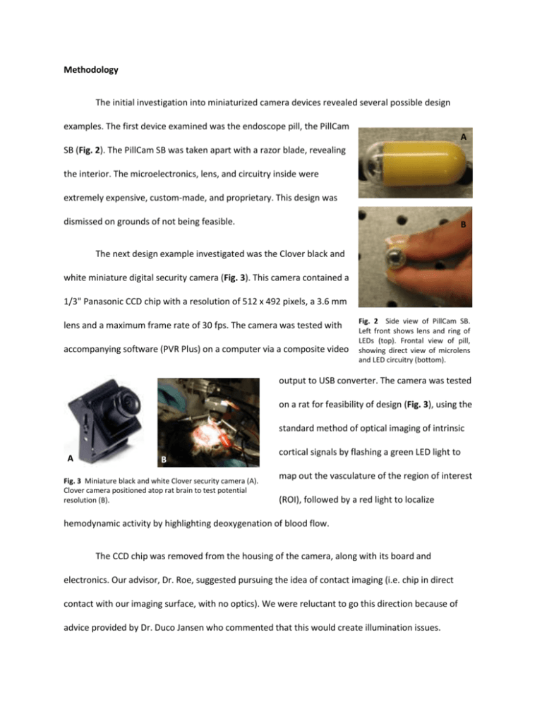
Methodology The initial investigation into miniaturized camera devices revealed several possible design examples. The first device examined was the endoscope pill, the PillCam A SB (Fig. 2). The PillCam SB was taken apart with a razor blade, revealing the interior. The microelectronics, lens, and circuitry inside were extremely expensive, custom-made, and proprietary. This design was dismissed on grounds of not being feasible. B The next design example investigated was the Clover black and white miniature digital security camera (Fig. 3). This camera contained a 1/3" Panasonic CCD chip with a resolution of 512 x 492 pixels, a 3.6 mm lens and a maximum frame rate of 30 fps. The camera was tested with accompanying software (PVR Plus) on a computer via a composite video Fig. 2 Side view of PillCam SB. Left front shows lens and ring of LEDs (top). Frontal view of pill, showing direct view of microlens and LED circuitry (bottom). output to USB converter. The camera was tested on a rat for feasibility of design (Fig. 3), using the standard method of optical imaging of intrinsic A B B Fig. 3 Miniature black and white Clover security camera (A). Clover camera positioned atop rat brain to test potential resolution (B). cortical signals by flashing a green LED light to map out the vasculature of the region of interest (ROI), followed by a red light to localize hemodynamic activity by highlighting deoxygenation of blood flow. The CCD chip was removed from the housing of the camera, along with its board and electronics. Our advisor, Dr. Roe, suggested pursuing the idea of contact imaging (i.e. chip in direct contact with our imaging surface, with no optics). We were reluctant to go this direction because of advice provided by Dr. Duco Jansen who commented that this would create illumination issues. A However, at the urging of our advisor, the chip was tested in direct contact with two different surfaces: a very thin slice of pig liver tissue plated on a slide, and a 1/2" thick piece of chicken liver obtained from a A supermarket (Fig. 4). The next step involved attempting to solve the problem of direct illumination, eliminating shadows and light pools. Dr. Jansen recommended that we employ a beamsplitter, with which direct illumination could be B Fig. 4 (A) Contact imaging of chicken liver piece with Panasonic CCD chip on top of glass slide, with red LED lights. (B) Tissue slide of pig liver used. provided with conventional optical techniques in an onboard approach. A beamsplitter would resolve difficulties of traditional optics by decoupling the axis of illumination from the axis of focal length, allowing for direct and unimpeded illumination of the brain while maintaining a device profile that is suitable for animal use and achievable with more accessible components. A 50R/50T mounted plate beamsplitter was obtained to attempt to implement a single light source, eliminating pooling on the tissue surface. With a lens in place, high resolution could be achieved (with adjustable focal distance). A compact design was the goal, with components going in a direction parallel to the surface of the brain. The first rough prototype we built was a large, scalable model in which an LED light source, along with the Clover camera’s Fig. 5 First prototype; built with 50R/50T beamsplitter, clamps, Camera, and Plexiglas base. Shown with LED light positioned where light source would go (base is where subject would be). CCD chip and lens were held in place by clamps screwed onto a Plexiglas base (Fig. 5). The design was judged to be appropriate by our advisors to miniaturize with smaller, easily-obtained materials. However, the ideal chip and lens would not be obtainable for our design. A simple schematic is shown in Fig. 6. Fig. 6 Schematics of 3 design generations. (A) Lensless system. CCD chip sits directly on a transparent membrane on the cortex; illumination poses an issue – where would light enter the system? (B) Simplified and minified version of a modern system. (C) Utilization of a beam-splitter allows for better use of 3D space and allows for the light source to be directly above the region of interest. We decided to build our system on a smaller scale using a larger lens and custom-made parts. A 2.6 cm lens, CCD chip (from the Clover camera), and a 75R/25T beamsplitter were to be the main components of the new design. We Fig. 8 Configuration of ThorlabTM cage system parts – from left to right – beamsplitter/holder, lens, CCD Chip. Yellow arrows indicate where light enters. Red arrows show 75R/25T signal Fig. 7 SolidWorks design of custom, lightweight, aluminum, beamsplitter holder (45o angle). Yellow arrow indicates where beamsplitter lays. designed a lightweight aluminum mount that would hold the beamsplitter at a 45° angle using SolidWorks, and had it made in the Vanderbilt University Physics Department machine shop (Fig. 7). We obtained Thorlabs, Inc. cage system parts that we used to hold the three main components in a linear manner using rails (Fig. 8). Using the thin lens equation, the distance from object to lens, lens to chip, and magnification was calculated by fixing the distance from object to beamsplitter to lens (7 cm + 4 cm = 11 cm) in order to obtain the clearest image possible (fixing S1_2 and S2_2 in Fig 9 and Fig 10 and calculating S1) (Fig. 9). The configuration of the parts is shown in a schematic (Fig. 10). The prototype was configured such that light source was positioned directly above the beamsplitter, which allowed for light to reach the surface to be imaged directly below. The reflected light signal then reached the CCD chip via the 75R/25T beamsplitter, allowing maximum image signal to be obtained. This configuration used horizontal space rather than vertical space, as desired. Several test images were obtained using the setup shown in Fig. 11. The composite video signal was converted to USB via DAZZLE Thin Lens Equation: 1/S1 + 1/S2 = 1/f 1/S1 + 1/(S1_2+S2_2) = 1/f 1/S1 + 1/(4+7) cm = 1/2.6 cm S1 = 3.40 cm Magnification: M = -S2/S1 = -3.22 To map well size onto CCD, set minimum chip width: w = 2*r w/2r = M = -S2/S1 Fig. 9 Calculations used to obtain object- lens-chip distances (Fig 10), and projected magnification. hardware (Avid Technology, Mountain View, CA), and observed on Pinnacle DVD maker software (Avid Technology, Mountain View, CA). The final prototype was tested on several different objects to obtain confirmation of accurate distance configurations before being tested in the laboratory on squirrel and macaque monkeys. The setup was easily transportable into the testing area, and footage was obtained with the final design. Group members were tested for tuberculosis prior to entering the testing area, as required by animal testing policy. Light Source 2.5 cm S1_2 = 4.00 cm 8.50 cm VideoUSB Converter S1 = 3.40 cm A B C 10 cm S1_1 = 7.00 cm Reflected Light 6 cm 15.75 cm Fig. 10 (A) Clover security camera CCD chip within ThorLab cage system part, (B) 2.6 cm lens, (C) and custom-made 45o aluminum beamsplitter (75R/25T) holder. Fig. 11 Setup of software, video to USB converter, and designed camera used to obtain images.


