doc00009
advertisement

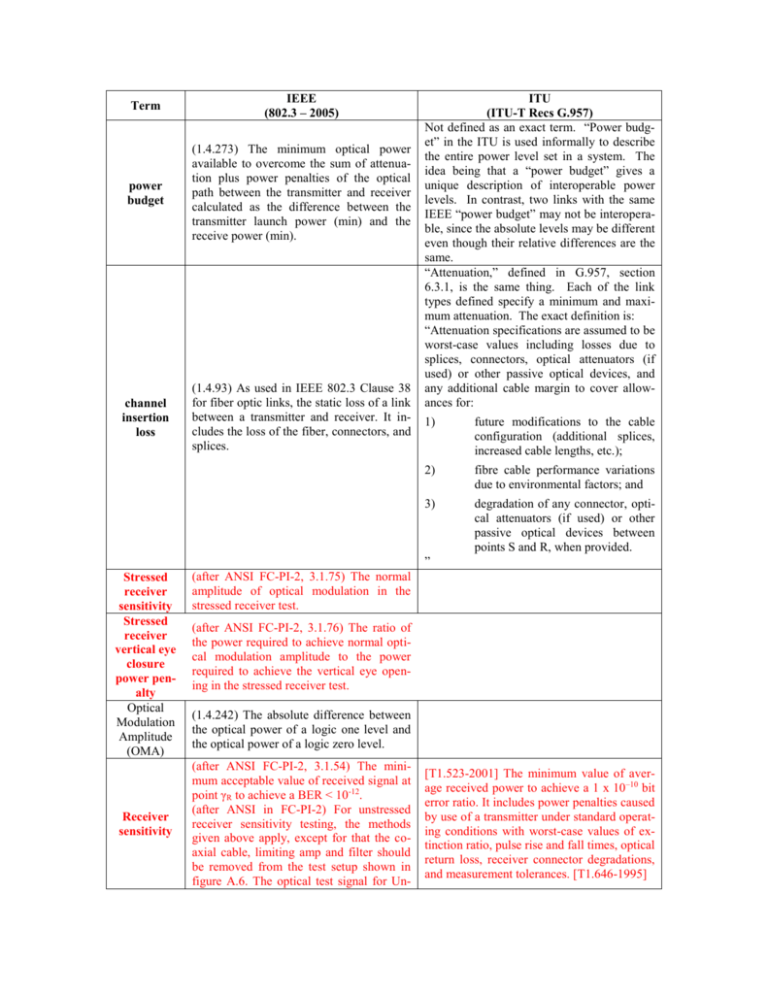
Term IEEE (802.3 – 2005) power budget (1.4.273) The minimum optical power available to overcome the sum of attenuation plus power penalties of the optical path between the transmitter and receiver calculated as the difference between the transmitter launch power (min) and the receive power (min). channel insertion loss (1.4.93) As used in IEEE 802.3 Clause 38 for fiber optic links, the static loss of a link between a transmitter and receiver. It includes the loss of the fiber, connectors, and splices. ITU (ITU-T Recs G.957) Not defined as an exact term. “Power budget” in the ITU is used informally to describe the entire power level set in a system. The idea being that a “power budget” gives a unique description of interoperable power levels. In contrast, two links with the same IEEE “power budget” may not be interoperable, since the absolute levels may be different even though their relative differences are the same. “Attenuation,” defined in G.957, section 6.3.1, is the same thing. Each of the link types defined specify a minimum and maximum attenuation. The exact definition is: “Attenuation specifications are assumed to be worst-case values including losses due to splices, connectors, optical attenuators (if used) or other passive optical devices, and any additional cable margin to cover allowances for: 1) future modifications to the cable configuration (additional splices, increased cable lengths, etc.); 2) fibre cable performance variations due to environmental factors; and 3) degradation of any connector, optical attenuators (if used) or other passive optical devices between points S and R, when provided. ” Stressed receiver sensitivity Stressed receiver vertical eye closure power penalty Optical Modulation Amplitude (OMA) Receiver sensitivity (after ANSI FC-PI-2, 3.1.75) The normal amplitude of optical modulation in the stressed receiver test. (after ANSI FC-PI-2, 3.1.76) The ratio of the power required to achieve normal optical modulation amplitude to the power required to achieve the vertical eye opening in the stressed receiver test. (1.4.242) The absolute difference between the optical power of a logic one level and the optical power of a logic zero level. (after ANSI FC-PI-2, 3.1.54) The minimum acceptable value of received signal at point γR to achieve a BER < 10-12. (after ANSI in FC-PI-2) For unstressed receiver sensitivity testing, the methods given above apply, except for that the coaxial cable, limiting amp and filter should be removed from the test setup shown in figure A.6. The optical test signal for Un- [T1.523-2001] The minimum value of average received power to achieve a 1 x 10–10 bit error ratio. It includes power penalties caused by use of a transmitter under standard operating conditions with worst-case values of extinction ratio, pulse rise and fall times, optical return loss, receiver connector degradations, and measurement tolerances. [T1.646-1995] stressed sensitivity testing should have low jitter, low vertical closure and noise, and rise and fall times faster than 0.3 UI (20 80%). Only the optical attenuator is used to degrade the input test signal. Damage threshold (max) Receiver sensitivity OMA (max) Minimum launch power Maximum launch power Not found Not found Not found Not found Average launch power (min) (e.g. Table 52–7) This term is informative and not the principal indicator of signal strength. A transmitter with launch power below this value cannot be compliant; however, a value above this does not ensure compliance Optical modulation amplitude (OMA) (58.7.6) This term is defined as the difference between light levels for “1” and “0”. extinction ratio (1.4.150) The ratio of the low optical power level to the high optical power level on an optical segment. (See IEEE 802.3, Clause 15.) eye-opening penalty (1.4.151) The difference, in dB, between (a) the optical power measured at the center of the data eye, and (b) the optical power measured at a point defined by the total worst-case peak-to-peak jitter at the receiver. link penalties (1.4.197) For fiber optic links, the power penalties of a link not attributed to link attenuation. These power penalties include modal noise, relative intensity noise (RIN), intersymbolic interference (ISI), mode partition noise, extinction ratio, and eyeopening penalties. Same definition, G.957, section 6.2.4 Not defined as an exact term. Fundamentally, the ITU specifications require that the Tx must have an eye that meets the mask, and that the Rx must have the sensitivity with a Tx signal that just meets the mask. I believe the ITU spec avoids defining this number because it is too dependent on exact pulse shape and implementation. This is a big source of difference. The closest thing is “Optical Path Penalty” defined in G.957, section 6.4.4. “The receiver is required to tolerate an optical path penalty not exceeding 1 dB (2 dB for L-16.2) to account for total degradations due to reflections, intersymbol interference, mode partition noise, and laser chirp.” Fundamentally, the ITU definition focuses on the penalty that is caused by going over the optical path, as opposed to just pure attenuation. This definition differs from the IEEE definition in that it does not include RIN, extinction ratio, eye-opening penalties, and, to some extent, ISI, if that ISI is electronic in nature, and not as a result of fiber dispersion. Those are pretty significant differences. In the ITU method, these impairments are accounted for in the specification of the Tx and Rx values. In contrast, the IEEE Tx and Rx values are more of an ‘ideal case’ number, to which the above impairments are deducted. Of course, the final result is much the same. It is just the way that the impairments are grouped together. Transmitter and Dispersion penalty (TDP) Defined by reference to the test procedure of clause 58.7.9, which states that a port transmitting the appropriate test pattern test shall meet specifications according to the methods specified below. The transmitter and dispersion penalty (TDP) measurement tests for transmitter impairments with chromatic effects for a transmitter to be used with single-mode fiber, and for transmitter impairments with modal (not chromatic) dispersion effects for a transmitter to be used with multimode fiber. Possible causes of impairment include intersymbol interference, jitter, RIN and mode partition noise. Meeting the separate requirements (e.g., eye mask, spectral characteristics) does not in itself guarantee the TDP. The procedure tests for pattern dependent effects; for 100BASE-LX10 and 100BASE-BX10, a standardized element of pattern dependent baseline wander is included in the reference channel. A mode detailed description follows in clause 58.7.9. Wish list ?? Term ISI (intersymbol interference) Dispersion IEEE (no reference) The effect on a sequence of symbols in which the symbols are distorted by transmission through a limited bandwidth medium to the extent that adjacent symbols interfere with each other. A term used to denote pulse broadening and distortion. The two general categories of dispersion are modal dispersion, due to the difference in the propagation velocity of the propagation modes in a multimode fiber, and chromatic dispersion, due to the difference in propagation of the various spectral components of the optical source. Similar effects ITU (???) Extinction Ratio Penalty Relative intensity noise (RIN) penalty Reflection noise penalty Baseline wander penalty Interaction penalty exist in electrical media when the velocity of propagation of the spectral components of a non-sinusoidal signal are not constant over frequency. An extinction ratio power penalty occurs when a nonzero power level is transmitted during a "0" symbol. RIN induced power penalty occurs due to the fluctuations in the output intensity of the laser source in the Tx module. In the case of single-mode lasers, interferometric noise will occur at the receiver. Interferometric or reflection noise results from the interference of the desired signal and its reflections at the receiver For scrambled binary pulse amplitude modulation (PAM-2) base line wander has a Gaussian distribution and is exacerbated by the ISI effects. For Gaussian noise terms the total noise variance is given by the sum of the variances of the individual noise terms. Thus the total power penalty, in dB, is not the simple sum of the individual power penalties. Additionally, ISI will exacerbate the penalty. Usually, the interaction or cross term is closely approximated by the summation of power penalties (in dB). Contributors (ordered alphabetically against the first name): Frank Effenberger Marek Hajduczenia Mike Dudek Paul Kolesar


