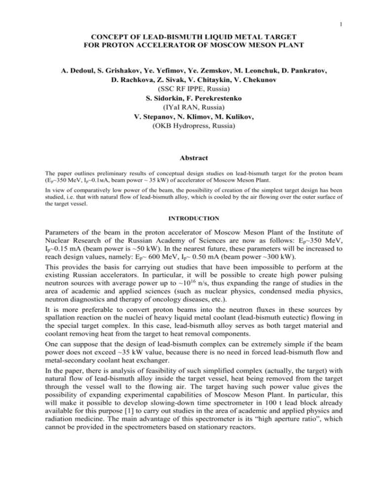
Fig. 1. - Physics
advertisement

1 CONCEPT OF LEAD-BISMUTH LIQUID METAL TARGET FOR PROTON ACCELERATOR OF MOSCOW MESON PLANT A. Dedoul, S. Grishakov, Ye. Yefimov, Ye. Zemskov, M. Leonchuk, D. Pankratov, D. Rachkova, Z. Sivak, V. Chitaykin, V. Chekunov (SSC RF IPPE, Russia) S. Sidorkin, F. Perekrestenko (IYaI RAN, Russia) V. Stepanov, N. Klimov, M. Kulikov, (OKB Hydropress, Russia) Abstract The paper outlines preliminary results of conceptual design studies on lead-bismuth target for the proton beam (Ep~350 MeV, Ip~0.1мA, beam power ~ 35 kW) of accelerator of Moscow Meson Plant. In view of comparatively low power of the beam, the possibility of creation of the simplest target design has been studied, i.e. that with natural flow of lead-bismuth alloy, which is cooled by the air flowing over the outer surface of the target vessel. INTRODUCTION Parameters of the beam in the proton accelerator of Moscow Meson Plant of the Institute of Nuclear Research of the Russian Academy of Sciences are now as follows: Ep~350 MeV, Ip~0.15 mA (beam power is ~50 kW). In the nearest future, these parameters will be increased to reach design values, namely: Ep~ 600 MeV, Ip~ 0.50 mA (beam power ~300 kW). This provides the basis for carrying out studies that have been impossible to perform at the existing Russian accelerators. In particular, it will be possible to create high power pulsing neutron sources with average power up to ~1016 n/s, thus expanding the range of studies in the area of academic and applied sciences (such as nuclear physics, condensed media physics, neutron diagnostics and therapy of oncology diseases, etc.). It is more preferable to convert proton beams into the neutron fluxes in these sources by spallation reaction on the nuclei of heavy liquid metal coolant (lead-bismuth eutectic) flowing in the special target complex. In this case, lead-bismuth alloy serves as both target material and coolant removing heat from the target to heat removal components. One can suppose that the design of lead-bismuth complex can be extremely simple if the beam power does not exceed ~35 kW value, because there is no need in forced lead-bismuth flow and metal-secondary coolant heat exchanger. In the paper, there is analysis of feasibility of such simplified complex (actually, the target) with natural flow of lead-bismuth alloy inside the target vessel, heat being removed from the target through the vessel wall to the flowing air. The target having such power value gives the possibility of expanding experimental capabilities of Moscow Meson Plant. In particular, this will make it possible to develop slowing-down time spectrometer in 100 t lead block already available for this purpose [1] to carry out studies in the area of academic and applied physics and radiation medicine. The main advantage of this spectrometer is its “high aperture ratio”, which cannot be provided in the spectrometers based on stationary reactors. 2 1. DESCRIPTION OF TARGET DESIGN Sketch of the target design is presented in Fig. 1. air air proton beam Fig. 1. Thin-walled cylindrical steel vessel of the target of ~155 mm in diameter having wall thickness of ~1.0 mm in its lower section is suspended from the flange of the target head fixed on support plate resting on the lead block. Aluminum safety jacket of 1.0 mm thickness is provided over the vessel to prevent radioactive lead-bismuth coolant release to the atmosphere in case of failure of the target vessel. Space between the main vessel and safety jacket (1.5 mm gap) is filled with helium. In order to provide coolant circulation inside the target, 92 mm diameter, 770 mm long tube is aligned in the target vessel forming upcomer section of the circuit, while the downcomer section is formed in the space between the internal tube and the main vessel wall. In the upcomer section, 12 mm diameter, 400 mm long sectionalized electric heater is embedded into the target to provide initial directed melting of the alloy in the target (starting from free level) and facilitate natural flow of the alloy until the proton beam is supplied to the target. The power of heater is 30 kW. Proton beam is supplied horizontally to the lateral surface of the target at its bottom. Energy absorbed in the target coolant is removed through the target vessel wall to the air flowing upwards in 15 mm thick gap between the target wall and the lead block to the special ventilation system. In order to facilitate heat removal from the target section upon which proton beam comes (in the area of windows in the safety jacket and the main target vessel) cooling air is supplied to the heat removal channel through the orifice installed coaxially to the proton beam. 3 Target head is equipped with tight bushings for electric cable of the heater and cables of thermocouples measuring alloy temperature distribution in the target, and nozzles would be attached, if necessary, serving as inlet and outlet for gas mixtures taken from the external coolant technology system. It is supposed for the future to study on the possibility of elimination of this gas mixture supply to the target. In this case, the target would be gas tight system, and all procedures on the coolant technology would be reduced to assurance of necessary coolant quality prior to filling target vessel. In case of axially symmetrical target design, its lifetime can be extended (provided that its position is vertical) owing to the possibility of relocation of irradiated area (window) of the target by means of discrete rotation of the vessel around its axis. 2. RESULTS OF EVALUATION OF TARGET PARAMETERS 2.1. Power rating of the target Target power rating was evaluated using LAHET (LCS) code. Configuration of the calculation model is presented in Fig. 2. Fig. 2. Cross section of the calculation model of the target Proton beam parameters assumed for analysis: Ep=350 MeV, Ip=0.1 mA, Gaussian distribution of protons over the beam radius with =1.5 cm. Table 1 gives typical power density values in the entire volume of the target, at the point of maximum power density value in lead-bismuth alloy and in the target vessel window. Table 1. Total power of the target 29.612 kW Maximum power density in the window (vessel) of the target 1.1853108 W/m3 Maximum power density in the “plume” volume in Pb-Bi 1.206108 W/m3 Power profile of the target along the beam axis is shown in Fig. 3. 4 10 8 8 6 6 R, cm R, cm 10 4 1.267 -- 1.400 1.133 -- 1.267 1.000 -- 1.133 0.8667 -- 1.000 0.7333 -- 0.8667 0.6000 -- 0.7333 0.4667 -- 0.6000 0.3333 -- 0.4667 0.2000 -- 0.3333 0.0667 -- 0.2000 -0.0667 -- 0.0667 -0.2000 -- -0.0667 4 2 1.267 -- 1.400 1.133 -- 1.267 1.000 -- 1.133 0.8667 -- 1.000 0.7333 -- 0.8667 0.6000 -- 0.7333 0.4667 -- 0.6000 0.3333 -- 0.4667 0.2000 -- 0.3333 0.0667 -- 0.2000 -0.0667 -- 0.0667 -0.2000 -- -0.0667 2 Beam 0 Z, cm 0 0 10 20 0 10 30 20 40 Z, cm 30 40 Z, cm Fig. 3. Shape of the power profile “plume” of the target along the beam axis 2.2. Evaluation of spallation and leakage neutron spectra Neutron spectra were evaluated for the vertical fragment of the target, i.e. lead-bismuth cylinder of ~7.5 cm radius and 20 cm length. Proton beam came to the central area of lateral cylindrical surface. Table 2 presents integral values characterizing neutron production and leakage. Таблица 2. Integral characteristics of neutron production and leakage Proton energy, MeV Number of neutrons produced in hadronnuclear cascade, neutron/proton Number of neutrons leaking through the upper surface of the target, neutron/proton 350 5.111 4.978 Related spectra are presented in Fig. 4. spallat 10 leakage 1 Neutron/proton 0,1 0,01 1E-3 1E-4 1E-5 1E-6 1E-5 1E-4 1E-3 0,01 0,1 1 10 100 1000 Energy, mev Fig. 4. Energy spectra of neutrons produced in the target and leakage neutrons 5 The results show that parasitic neutron absorption of the target is low. 2.3. Evaluation of activation and radioactive decay in the target In order to evaluate induced activity in the target and its evolution during the period up to 106 years, comprehensive analysis was made using LAHET, MCNP-4b and ORIGEN2 code packages and the library of decay characteristics: DECAY, LIB included in ORIGEN2. The total radioactivity of the target at the end of one year irradiation cycle (360 days), induced by 6.241014 proton/s flux is equal to R=2.29103 Ci. Figs. 5 and 6 present plots of radioactivity build-up in the target under irradiation and its post-irradiation behavior in time, the results being normalized on 1010 proton/s basis. Both total activity and its components caused by nuclides with the highest contribution. CURIES 0 10 -1 10 -2 10 -3 10 -4 10 -5 10 -6 10 -7 10 -8 10 -9 10 -10 10 -11 10 -12 10 -13 10 -14 10 -15 10 -16 10 -17 10 -18 10 -19 10 Total SR 90 TL206 PO 210 PB209 BI208 BI210 H G 205 10 -7 10 -6 10 -5 10 -4 10 -3 10 -2 10 -1 10 0 10 1 10 2 T IM E , day Fig. 5. Radioactivity build-up in the target caused by its irradiation by protons CURIES 10 0 Total 10 -1 10 -2 10 -3 PO 210 10 -4 PB209 10 -5 BI208 10 -6 10 -7 10 -8 10 -9 SR 90 TL206 BI210 H G 205 10 -10 10 -11 10 -12 10 -13 10 -14 10 -15 10 -4 10 -3 10 -2 10 -1 10 0 10 1 10 2 10 3 10 4 10 5 10 6 10 7 10 T IM E , d a y Fig. 6. Post-irradiation target activity 8 10 9 10 10 6 2.4. Evaluation of dpa parameter and gaseous products accumulation Evaluation has been made for 360 days period of target operation corresponding to 1.94 1022 proton fluence. Table 3 gives maximum dpa values and maximum total amounts of accumulated gaseous products (hydrogen and helium) in the window of target vessel. Table 3. Maximum dpa values and maximum build-up of gas products in the window of the target vessel Maximum dpa value 2.3 Maximum hydrogen build-up, ppm 1120 Maximum helium build-up, ppm 145.2 2.5. Analysis of the target thermohydraulics Analysis of thermohydraulic characteristics of the target (Fig.1) was made using RFZ three-dimensional code [2] based on numerical method of solution of the system of differential equations of hydrodynamics and heat transfer in (r, , z) – geometry. It is supposed to put the target into operation in two stages. On the first stage, natural flow of liquid metal should be “driven up” by means of heat supplied by the heater. On the second stage, liquid metal flow is caused by only power rating in the target alloy under irradiation by the proton beam. Analysis of thermohydraulics of the coolant natural flow in the target has been made in order to determine dynamics of natural flow increase and confirmation of possibility of heat removal from the target (~30 kW) through the target vessel wall. For this purpose, target design was simulated by cylindrical calculation domain with axial, radial and angular difference grids. The number of radial, axial and azimuthal nods is respectively equal to nr = 49, nz = 166 and n= 42. The total number of calculation nods is equal to n=341628. Results of analysis of the first stage of target temperature increase are presented in Fig. 7 where coolant velocity field caused by the heater is shown. It can be seen from the picture that the area of upward coolant flow has been formed in the vicinity of heater. In this area, maximum coolant velocity equal to w = 0.45m/s is reached at the elevation located 0.1m over the heater top. Downward coolant flow is formed near the internal wall of the target vessel. 7 0.60 0.40 Z, м Z, м 1.10 0.20 0.90 0.00 0.00 0.70 0.00 R, м а) R, м b) Fig. 7. Steady state coolant velocity patterns in the target heated by heater а) target lower section; b) target upper section. Upon reaching steady state patterns of coolant velocity, pressure and temperature in the target, analysis was suspended, and power rating pattern caused by heater was replaced by that caused by proton beam. Then the analysis of the second (main) stage of target operation under proton beam irradiation was performed. Figs. 8 and 9 present intermediate results of this stage analysis, since steady state profiles of coolant velocity and temperature in the target had not been reached by the time of this paper preparation. 8 0.60 1.20 Z, м Z, м 0.40 1.00 0.20 0.80 0.00 0.00 0.08 R, м а) 0.00 0.08 R, м b) Fig. 8. Intermediate results of analysis of alloy velocity profile in the target irradiated by the proton beam (transient conditions): а) lower section of the target b) upper section of the target. Fig. 8 shows coolant velocity pattern caused by the power rating in the alloy, which is somewhat different from that obtained for the initial heating stage. There is some change in the dimension of the coolant recirculation area on the wall of the tube forming upward flow. Maximum velocity has reached 0.55 m/s value, and its position in the target has become 0.2 m lower. Temperature field of target coolant in the area irradiated by the beam is heterogeneous because of the power profile in this area (Fig. 9). The hottest point of the coolant (~750С) is located in this area. 9 Results of analysis of dynamics of temperature and velocity profiles show that steady state temperatures would hopefully be much lower than this value, and so these temperatures would be acceptable from the standpoint of corrosion behavior of structural materials in leadbismuth alloy. 1.20 1.00 700 650 600 550 0.80 500 Z, м 450 400 350 0.60 300 250 200 150 0.40 100 50 0 0.20 0.00 0.00 R, м Fig. 9. Intermediate results of analysis of temperature field in the target irradiated by the beam (transient conditions) Average velocity of the cooling air in the annular gap between cavity wall and safety jacket of the target, is 100 m/s, and temperature rise of the air reaching the outlet cross section is ~40С. 10 Conclusion Conceptual studies have shown that for the proton beam of power up to 35 kW, it is apparently possible to create a simple design of lead-bismuth target using natural flow of leadbismuth coolant, power being removed from the target through the vessel wall to the air flowing outside assuring acceptable level of temperatures of structural materials and alloy. Analytical studies on the target thermohydraulics are under way. References 1. S. Sidorkin, A. Perekrestenko, et al, Neutron slowing-down time spectrometer based on measurements in lead. Paper submitted to this Conference. 2. S. Grishakov, M. Leonchuk, Updated methods of three-dimensional analysis of hydrodynamics of nuclear reactor coolant path in (r,,z)-geometry. Preprint IPPE-2384, Obninsk, 1994.


