Report 7
advertisement
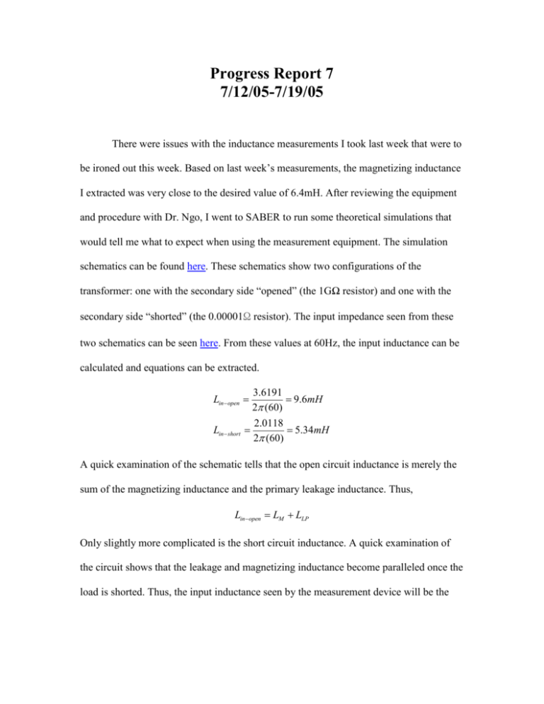
Progress Report 7 7/12/05-7/19/05 There were issues with the inductance measurements I took last week that were to be ironed out this week. Based on last week’s measurements, the magnetizing inductance I extracted was very close to the desired value of 6.4mH. After reviewing the equipment and procedure with Dr. Ngo, I went to SABER to run some theoretical simulations that would tell me what to expect when using the measurement equipment. The simulation schematics can be found here. These schematics show two configurations of the transformer: one with the secondary side “opened” (the 1GΩ resistor) and one with the secondary side “shorted” (the 0.00001Ω resistor). The input impedance seen from these two schematics can be seen here. From these values at 60Hz, the input inductance can be calculated and equations can be extracted. 3.6191 9.6mH 2 (60) 2.0118 5.34mH 2 (60) Lin open Lin short A quick examination of the schematic tells that the open circuit inductance is merely the sum of the magnetizing inductance and the primary leakage inductance. Thus, Lin open LM LLP Only slightly more complicated is the short circuit inductance. A quick examination of the circuit shows that the leakage and magnetizing inductance become paralleled once the load is shorted. Thus, the input inductance seen by the measurement device will be the parallel combination of the secondary leakage and the magnetizing inductance summed with the primary leakage: Linshort LLP LM LLS These new results warranted a new round of measurements be conducted to ascertain the truth values for the transformer. Using the Wayne Kerr impedance analyzer set for 100mV at 60Hz, the transformer was tested again. This time the inductance measurements were taken solely from the inductance model, not the transformer model. First, the inductance was measured from the primary side with the secondary opened. Then, the secondary was shorted and the inductance was again measured. Finally, the secondary was measured with the primary opened. This was done to ensure the secondary leakage value was accurate, also. The table below gives all the data: Input L Primary (secondary Primary (secondary Secondary (Primary open) shorted) open) 6.61mH 3.41mH 6.63mH 6.61mH LM LLP 6.63mH LM LLS 3.41mH LLP LM LLS LM LLS 3.41mH (6.61mH LM ) LM *(6.63mH LM ) 6.63mH LM 4.61mH LLP 2mH , LLS 2.02mH The values for the current transformer are a 4.61mH magnetizing inductance and approximately 2mH of leakage inductance per side. While this is short of the expected 6.4mH of magnetizing inductance, it does show that the original assumption that the leakage would be half the magnetizing was fairly accurate. The next step is to integrate these values into the simulation to determine the value of the input capacitor that will still ensure the output of the rectifier will have 20V and 15W. Recall the schematic here. The inductors were replaced with their new values and the input capacitor was found to be 112uF. There are still issues that I will take up with Dr. Ngo tomorrow concerning the testing of the transformer. Chief among these concerns are the coupling of the data transmission primary to the power secondary, input current levels, and input resistance. Dan 7/12/05
