appendix a: sizing of distillation columns
advertisement
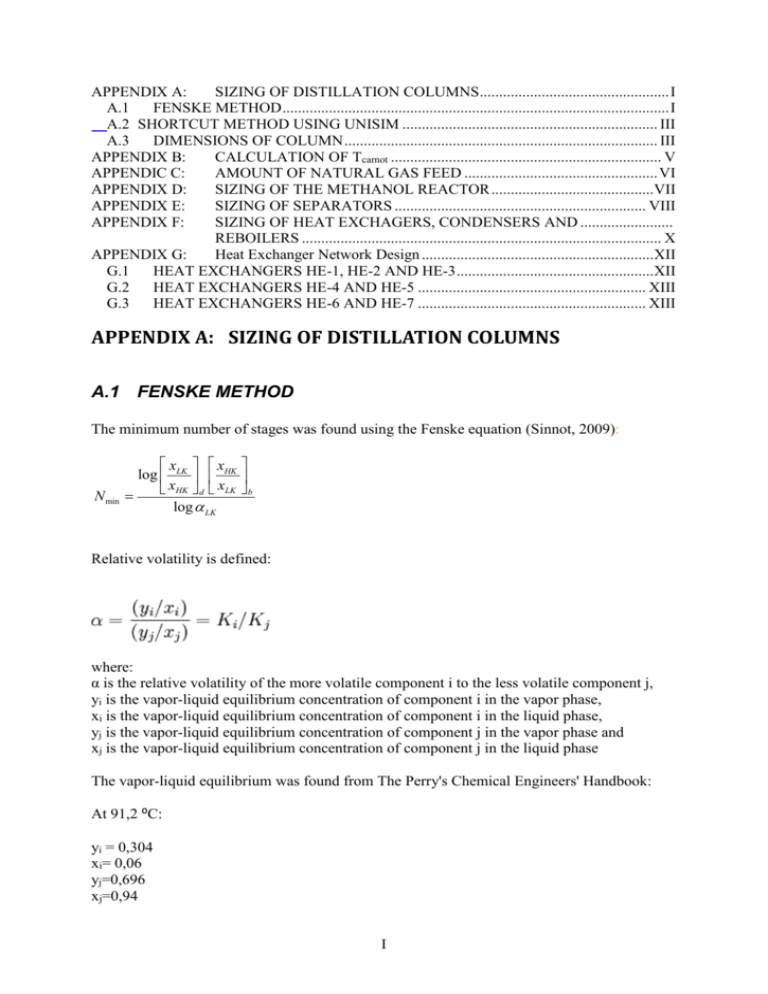
APPENDIX A: SIZING OF DISTILLATION COLUMNS ................................................. I A.1 FENSKE METHOD .................................................................................................... I A.2 SHORTCUT METHOD USING UNISIM .................................................................. III A.3 DIMENSIONS OF COLUMN ................................................................................. III APPENDIX B: CALCULATION OF Tcarnot ...................................................................... V APPENDIC C: AMOUNT OF NATURAL GAS FEED .................................................. VI APPENDIX D: SIZING OF THE METHANOL REACTOR ..........................................VII APPENDIX E: SIZING OF SEPARATORS ................................................................. VIII APPENDIX F: SIZING OF HEAT EXCHAGERS, CONDENSERS AND ........................ REBOILERS ............................................................................................. X APPENDIX G: Heat Exchanger Network Design ............................................................XII G.1 HEAT EXCHANGERS HE-1, HE-2 AND HE-3 ...................................................XII G.2 HEAT EXCHANGERS HE-4 AND HE-5 ........................................................... XIII G.3 HEAT EXCHANGERS HE-6 AND HE-7 ........................................................... XIII APPENDIX A: SIZING OF DISTILLATION COLUMNS A.1 FENSKE METHOD The minimum number of stages was found using the Fenske equation (Sinnot, 2009): N min x x log LK HK xHK d xLK b log LK Relative volatility is defined: where: α is the relative volatility of the more volatile component i to the less volatile component j, yi is the vapor-liquid equilibrium concentration of component i in the vapor phase, xi is the vapor-liquid equilibrium concentration of component i in the liquid phase, yj is the vapor-liquid equilibrium concentration of component j in the vapor phase and xj is the vapor-liquid equilibrium concentration of component j in the liquid phase The vapor-liquid equilibrium was found from The Perry's Chemical Engineers' Handbook: At 91,2 ⁰C: yi = 0,304 xi= 0,06 yj=0,696 xj=0,94 I Thus the relative volatility was calculated to be 6,84 For the distillate: XLK=0,999 XHK=0,001 For the bottoms: XLK= 0,001 XHK=0,999 From the Fenske equation the minimum number of stages was calculate to be 7,2. A factor of three was assumed to get the real number of stages. Thus the number of stages became 22. II A.2 SHORTCUT METHOD USING UNISIM Using the shortcut module in UniSim and the specifications given in table A.1 the number of stages was calculated for COL-2. Assuming a stage efficiency of 60% the real number of stages was calculated. The result of the calculation is given in table A.2. The number of stages in COL-1 was calculated by using the distillation column module in UniSim. The flow molar flow rate from the reboiler was specified to be 0,997 of the total amount of methanol + water in the feed. The temperature in the condenser was set to 18 °C. The number of stages and feed stage was found using trial and error until the CO2 mole fraction was near zero in the bottom stream and until the recycle ratio was reasonable. Table A.1 - Specifications used in the short cut column Water in distillate [mole fraction] Methanol in Bottoms[mole fraction] Condenser pressure[kPa] Reboiler pressure [kPa] External reflux ratio COL-2 0,001 0,001 100 200 0,68* *Set to 1,2 times the minimum reflux ratio (IA1) Table A.2 – Result of calculation Number of stages –reboiler Number of stages with 60 % Efficiency Feed stage (from the top) COL-1 27 45 COL-2 6 10 11 Reboiler A.3 DIMENSIONS OF COLUMN The columns was sized using a procedure described by Sinnot. Procedure from Sinnot: The plate spacing was set to 0,5 m. The column diameter was calculated according to the following equations: v u v (0,17l 0, 27lt 0, 047) L v ^ 2 t III 0,5 ^ Where u v is the maximum allowable vapor velocity, based on the gross (total) column cross sectional area, m/s, and lt is the plate spacing in meters. Dc 4Vˆw v uˆv Where Dc is the column diameter in meters, Vˆw is the maximum vapor rate in kg/s. IV APPENDIX B: CALCULATION OF Tcarnot The temperature where the reaction changes from being non-spontaneous to spontaneous is called TCarnot. TCarnot was calculated using the relation: GRX H RX T SRX At equilibrium the equation above is equal to zero, and the Tcarnot could be calculated: Tcarnot H RX S RX Thermodynamic data for different pressures and temperatures was obtained from UniSIM and SI-chemical data. The data are listed in table B.1. The thermodynamic data in from table B.1 was used to calculate ΔHRX and ΔSRX for reaction B.1. The results are shown in table B.2. CH 4 ( g ) H 2O( g ) CO( g ) 3H 2 (B.1) Table B.1. Thermodynamic data collected at different temperatures and pressures. 298 K and 1 bar 200 C and 40 bar 800C and 40 bar H S H S H S Components CH4(g) CO(g) H2(g) H2O(g) [kJ/kgmol) -74920,00 -110600,00 -0,11 -245550,00 [kJ/kgmolC] 183,60 159,20 123,10 189,00 [kJ/kgmol) -68193,94 -105531,10 5038,69 -272048,48 [kJ/kgmolC] 170,74 141,82 105,62 90,71 [kJ/kgmol) -31150,49 -86367,16 22920,71 -213118,89 [kJ/kgmolC] 219,65 167,79 129,93 189,76 Table B.2. Tcarnot for different temperatures and pressures 298 K and 1 bar 200 C and 40 bar 800C and 40 bar ΔHRX [kJ/kgmol] 209870 249827 226664 ΔSRX [kJ/kgmolC] 156 197 148 Tcarnot [C] 1073 994 1257 It would seem that the temperature have to above 1257 ⁰ Celsius to make the reaction spontaneous. The Tcarnot seemed to vary quite a lot, which is a bit distubing, since one could expect that the Tcarnot should be relative constant because there are no phase transitions present. UniSIM are probably not be best tool to use, when collection thermodynamic data, but was used because of the simplicity. In the literature (S. Lee, 1997) thermodynamic calculations were done for the same reaction. The result was a Tcarnot temperature of 950K. The temperature in the steam was chosen to be 1000 °C to be sure that the reaction actually is above Tcarnot, and to ensure that reaction would give good conversion. The latter is especially important for the process described in this report, because of the lack of a secondary reformer. V APPENDIC C: AMOUNT OF NATURAL GAS FEED This appendix shows the calculation of the amount of natural gas feed needed for the process to produce 2500 tonne pr day methanol assuming 100% conversion, By combining the equations C.1 and C.2, equation can be formed: CH 4 ( g ) H 2O( g ) CO( g ) 3H 2 ( g ) (C.1) CO( g ) 2H 2 ( g ) CH 3OH ( g ) (C.2) CH 4 ( g ) H 2O( g ) CH3OH ( g ) H 2 ( g ) (C.3) From this equation it is easy to see that 1 mole of methanol is equivalent to 1 mole of methane. Using a molar mass of 32,0418 kg/kgmole methanol, the amount of methane required to make 2500 tonne/day methanol was found to be 3251kgmole/h. This value was used as an approximation of the amount of natural gas needed in the methanol production. VI APPENDIX D: SIZING OF THE METHANOL REACTOR The reaction of syngas to methanol is highly exothermic. Heat released from the reaction needs to be removed to keep the reactor isothermal. To be able to cool the reactor sufficient, the catalytic mass has to be divided into small enough pieces that heat efficiently can be removed. Tjeldbergodden has similar reactor and reaction, which is carried out at a similar temperature. The tube dimensions used at Tjeldbergodden were used as an estimate for the catalytic tubes size estimation. The reactor length was also assumed to be the same as used at Tjeldbergodden. In the industry, a 4:1 recycle ratio is commonly used (Aasberg-Petersen, 2001). The number of tubes needed in the reactor are based this recycle ratio, a single tube diameter of 4 cm (O7) and a maximum flow velocity of 5m/s (O4). A flow rate of 13199 kgmole/h incoming feed from the reformer section would result in a allowed recycle of 65995 kgmole/h. Which is equivalent to a volume flow rate of 16,88 m3/s when using a molar density of 1,09 kgmol/m3. A maximum allowable flow rate in the reactor lead to a cross section area of 6,75 m2 ,when assuming a catalyst void fraction of 0,5. This will lead to a total number of 5373 tubes inside the reactor shell. The outer diameter of the shell was calculated by assuming a triangular pitch of 1,25 times the outer tube diameter (Smith, 2005) and a wall thickness of 0,5 cm. A single tube in a triangular pitch arrangement was reported by the literature (Smith, 2005) to be contained in an area of 0,866 times the pitch squared. From this, the area and the diameter were calculated. The total diameter was found to be 4,8 m. VII APPENDIX E: SIZING OF SEPARATORS The size of the separators was calculated using the procedure described by Sinnot et. al (Sinnot, 2009). Sizing data from UniSIM was compared with the data from the procedure above. It was assumed that demister pads were used for both separators. The procedure from Sinnot et al goes as the following: Equation E.1 can be used to calculated the settling velocity (ut) : 1 ( v ) 2 ut 0, 07 L v (E.1) where L is the liquid density and v is the vapor density. Minimum vessel diameter: Dv 4Vv us (E.2) Where Vv is the volumetric flow rate in m3/s, us =ut since demister pads were used. Required liquid level was calculated by assuming a 10 min hold up time. The height were calculated according to figure 10,67 page 638 in Sinnot et. al (Sinnot, 2009). Key data are given in table E.1 VIII Table E.1 – Key data Variable SEP-1 SEP-2 0,67 0,39 ρL[kg/m3] 1004,6 821,4 ρv [kg/m3] 10,9 25,0 Vv[m/s] 3,10 9,33 Dv 2,43 5,49 Liquid height [m] 2,32 1,22 Liquid level to inlet (min(d/2,0.6m)) [m] 1,21 1,22 Inlet to demister pad (min(d,1m)) [m] 2,43 5,49 Demister pad to vapor outlet (min0.4m) [m] 0,40 0,40 Total height [m] 6,36 9,85 ut [m/s] IX APPENDIX F: SIZING OF HEAT EXCHAGERS, CONDENSERS AND REBOILERS This appendix describes the sizing of the heat exchangers, condensers and reboilers. Heat transfer coefficients for the fluids used in the model are given in table F.1. Table F.1 – Heat transfer coefficients (Skogestad, 2003) Heat transfer coefficients Fluids [W/m2 K] High pressure process stream- water 570 High pressure process stream –vaporizing water (assumed) 500 High pressure process stream –high pressure vapor 450 High pressure process stream- High pressure process stream 450 Low pressure process stream – Water 140 Boiling liquid- condensing vapor 800 Boiling liquid- Cooling of super heated steam (assumed) 800 The exchanger area was calculated by using the duty given from UniSIM. The log mean temperature difference was calculated for each heat exchanger. If one or both of the fluids experienced phase transitions, the exchanger was split into appropriate pieces such that correct heat transfer coefficients could be used. All heat exchangers are assumed to be counter-current heat exchangers. Example: Duty: Q (given from UniSIM) LMTD (log mean temperature difference) = T1 T2 T ln 1 T2 Where T1 is the temperature difference between the hot inlet stream and cold outlet is is stream and T2 is the difference between the hot outlet stream and the cold inlet stream. Using the relation: X A Q U * LMTD The heat exchanger area could then be calculated. The results are shown in table F.2. Table F.2 – Key heat exchanger data Heat exchanger (HE-1) Heat exchanger (HE-2) Heat exchanger (HE-3) Heat exchanger (HE-4) Heat exchanger (HE-5) Heat exchanger (HE-6) Heat exchanger (E-105) Reboiler (REB-1) Reboiler (REB-2) Condenser (CON-1) Condenser (CON-2) Duty [kW] Surface area [m2] Type Included in heat recovery unit on 28673 the steam reformer Included in heat recovery unit on 20360 the steam reformer Included in heat recovery unit on 121776 the steam reformer 61583 1321 U-tube 137072 13087 Flat plate 74205 2934 U-tube 133129 894 Falling film evaporator 9434 99 Kettle 59945 473 Kettle 262 163 Shell and tube 60620 7508 Shell and tube XI APPENDIX G: Heat Exchanger Network Design The synthesis gas (H1) from the steam reformer is to be cooled from 1000°C to 30°C. The product out from the methanol reactor (H2) is to be cooled from 260°C to 30°C. Flue gas from the steam reformer (H3) should be cooled from 1000°C to below 150°C The natural gas feed (C1) is to be heated from -0,26°C to 455°C. The methane rich gas from the prereformer (C2) is to be heated from 448,25°C to 650°C The methanol reactor feed (C3) is to be heated from 46,03°C to 260°C. Table G.1 summarizes the flow rate, heat capacity and temperature intervals for the six streams. Table G.1 – Properties for the hot and cold streams Stream Flow rate, m Cp (average) (kg/s) (kJ/kg°C) # C1 Natural Gas 15,21 3,047 C2 Methane from PR 51,74 2,744 C3 Reactor feed 286,49 2,648 H1 Exhaust gas 157,24 1,255 H2 Syngas 51,74 3,440 H3 Methanol 273,70 2,677 ΔT °C 455,26 201,75 213,97 850 970,00 230,00 Q = mCpΔT MW 21,10 28,64 162,32 177,53 172,66 168,53 G.1 HEAT EXCHANGERS HE-1, HE-2 AND HE-3 To ease the start-up of the plant, the flue gas (H3) is only heat integrated with the process streams before the steam reformer (C1 and C2). It should also be ckecked if there is enough heat in the flue gas to generate the amount of MP Steam needed in process. The dew point for water at 30 bar (pressure for MP steam) is 234,6°C. The heat of vaporization is 1822,70 kJ/kg. Generating MP steam with a flowrate of 36,351 kg/s and target temperature of 455°C requires a duty of QMP m(c p1T1 H vap c p 2 T2 ) 36,351 kg/s x (4,789 kJ/kgC x 224,37 C + 1822,70 kJ/kg + 2,249 kJ/kgC x 220,4 C) 123,94 MW The total required duty is then Q = QC1 + QC2 + QMP = 21,10 MW + 28,64 MW + 123,94 MW = 173,68 MW. Assuming an outlet temperature of 150°C for the flue gas, the cp is found to be 1,153 kJ/kg°C. At 1000°C the cp is 1,370 kJ/kg°C, and the average cp is then 1,262 kJ/kg°C. The outlet temperature of the flue gas becomes T Ts Q 173680kW 1000°C 125,8°C mc p 157, 24kg/s 1, 262kJ/kg°C XII At 125,8°C the cp is 1,147 kJ/kg°C, and the average cp is then 1,259 kJ/kg°C. The exit temperature then becomes 122,7°C which is an acceptable exit temperature. Further in the calculations, if nothing else is stated, cp is assumed to not change cignificantly for smaller temperature intervals. The outlet temperature of H3 out of HE-1 becomes T Ts Q 21100kW 1000°C 893,67°C mc p 157, 24kg/s 1, 262kJ/kg°C The outlet temperature of H3 out of HE-2 becomes T Ts Q 28640kW 893,67°C 749,34°C mc p 157, 24kg/s 1, 262kJ/kg°C G.2 HEAT EXCHANGERS HE-4 AND HE-5 The synthesis gas from the steam reformer could possibly be used to generate HP steam. The dew point for water at 40 bar (HP steam) is 251,3°C. The heat of vaporization is 1741,17 kJ/kg. Generating HP steam with a flowrate of 38,671 kg/s and target temperature of 510°C requires a duty of QHP m(c p1T1 H vap c p 2 T2 ) 38,671 kg/s x (5,517 kJ/kgC x (251,3-10) C + 1741,17 kJ/kg + 2,397 kJ/kgC x (510-251,3)C) 142,79 MW The excess heat for the syngas is (172,66-142,79) MW = 29,87 MW. The outlet temperature of the syngas becomes T Ts Q 142790kW 1000°C 197, 4°C mc p 51,74kg/s 3, 440kJ/kg°C To reach the target temperature of 30°C cooling water (duty = 29,87 MW) could be used (HE-5). Because there will be a phase transition, the heat exchanger will have a larger duty. G.3 HEAT EXCHANGERS HE-6 AND HE-7 The feed to the methanol reactor (C3) could be heat integrated with the methanol stream out of the methanol reactor (H3). The methanol stream has a dew point of 110,8°C. To ease the calculations, no phase transition is assumed during the heat exchange with the methanol reactor feed. Assuming a ΔTmin equal to 20°C, i.e. the outlet temperature of C3 to be 240°C, the duty for HE-6 becomes XIII Q 286, 49 kg/s 2,648 kJ/kgC (240 - 46,03) C 147,15 MW The duty of the cooler (HE-7) becomes (168,53-147,15) MW = 21,38 MW and the outlet temperature H3 becomes T Ts Q 147150kW 260°C 59,16°C mc p 273,70kg/s 2,677kJ/kg°C Because there will be a phase transition, the heat exchanger (HE-7) will have a larger duty. The duty of the heater becomes (assuming cp will not change significantly because of the small temperature difference) Q 286, 49 kg/s 2,648 kJ/kgC (260 - 240) C 15,17 MW In reality, since phase transition will occure, the outlet temperature of C3 will be lower and the duty of the heater will be higher, and the outlet temperature of H3 will be higher and therefore will also the duty of the cooler be higher. In figure G.2 below the proposed heat exchanger network is shown. Heat exchanger I represents, HE-1, II represents HE-2 and so on. HE-5 and HE-7 is replaced by the symbol C for cooling. Figure G.2 – Heat Exchanger Network Design XIV
