The PDR Document
advertisement
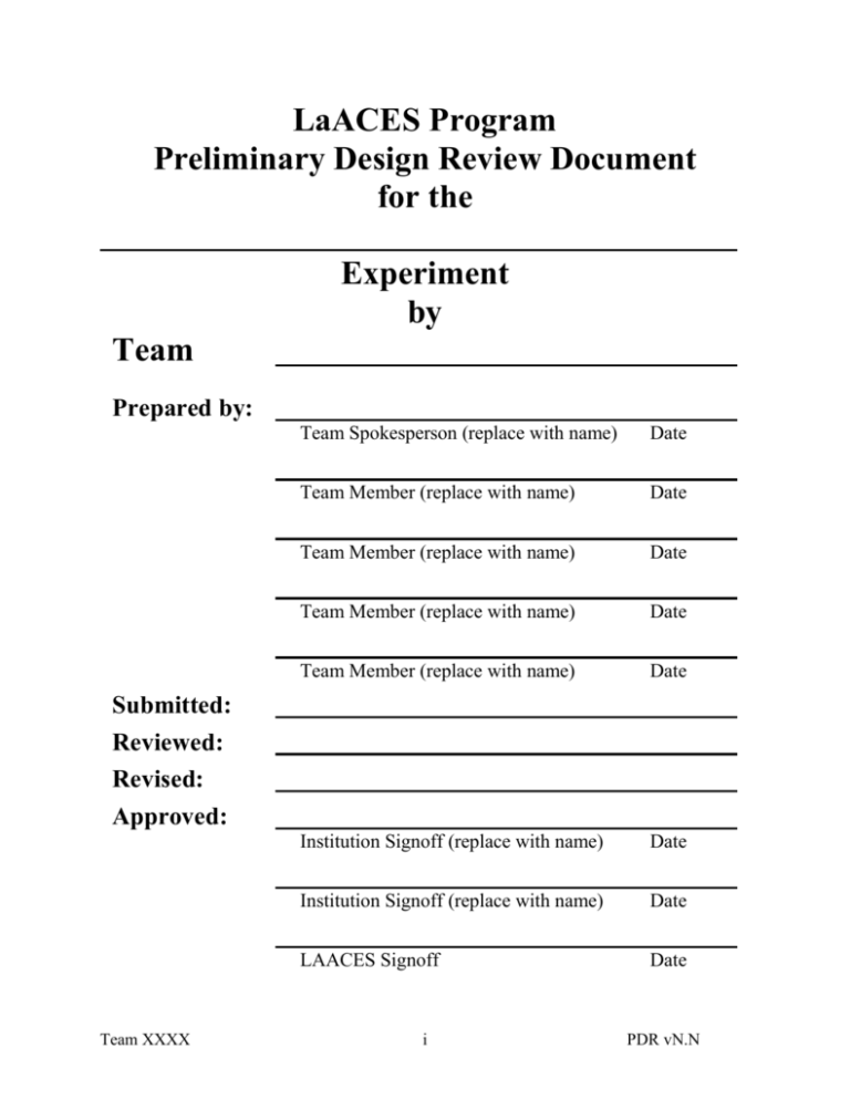
LaACES Program Preliminary Design Review Document for the Experiment by Team Prepared by: Team Spokesperson (replace with name) Date Team Member (replace with name) Date Team Member (replace with name) Date Team Member (replace with name) Date Team Member (replace with name) Date Institution Signoff (replace with name) Date Institution Signoff (replace with name) Date LAACES Signoff Date Submitted: Reviewed: Revised: Approved: Team XXXX i PDR vN.N TABLE OF CONTENTS Cover ............................................................................................................................................... Table of Contents ............................................................................................................................ List of Figures ................................................................................................................................. List of Tables .................................................................................................................................. 1.0 Document Purpose ..................................................................................................................1 1.1 Document Scope ...............................................................................................................1 1.2 Change Control and Update Procedures ...........................................................................1 2.0 Reference Documents .............................................................................................................1 3.0 Goals, Objectives, Requirements ............................................................................................1 3.1 Mission Goal .....................................................................................................................1 3.2 Objectives .........................................................................................................................1 3.3 Science Background and Requirements ...........................................................................2 3.4 Technical Background and Requirements ........................................................................2 4.0 Payload Design .......................................................................................................................3 4.1 Principle of Operation .......................................................................................................3 4.2 System Design ..................................................................................................................3 4.3 Electrical Design ...............................................................................................................4 4.4 Software Design ................................................................................................................5 4.5 Thermal Design .................................................................................................................5 4.6 Mechanical Design............................................................................................................5 5.0 Payload Development Plan .....................................................................................................6 8.0 Project Management ...............................................................................................................8 8.1 Organization and Responsibilities ....................................................................................8 8.2 Configuration Management Plan ......................................................................................8 8.3 Interface Control ...............................................................................................................8 9.0 Master Schedule ......................................................................................................................8 9.1 Work Breakdown Structure (WBS) ..................................................................................8 9.2 Staffing Plan......................................................................................................................9 9.3 Timeline and Milestones ...................................................................................................9 11.0 Risk Management and Contingency .....................................................................................9 12.0 Glossary .............................................................................................................................10 PDR Note: Sections 6, 7 and 10 will be provide in a later document. In addition, for PDR some sections of 4 and 9 need to be partially completed (see details in sections 4 & 9). Team XXXX ii PDR vN.N LIST OF FIGURES 1. Figure on expected science results ............................................................................................3 2. Drawing of payload design .......................................................................................................4 3. Block diagram of payload systems ...........................................................................................4 4. Schematic of detector electronics .............................................................................................4 5. Schematics of power system .....................................................................................................4 6. Flight software flow chart .........................................................................................................4 7. Drawing of mechanical details..................................................................................................4 8. Flow chart of payload development ..........................................................................................5 12. Project organization chart .......................................................................................................8 13. Project timeline diagram .........................................................................................................9 Team XXXX iii PDR vN.N LIST OF TABLES 1. Table of science and technical goals .........................................................................................3 2. Goals versus measurement traceability matrix .........................................................................4 3. Power budget table ....................................................................................................................4 4. Weight budget table ..................................................................................................................4 7. Data rates and storage requirements .........................................................................................7 9. Work breakdown structure ........................................................................................................9 12. List of risk items ...................................................................................................................11 Team XXXX iv PDR vN.N 1.0 Document Purpose NOTE: The section should have been completed for the Pre-PDR. Therefore, you should be able to “cut and paste” all sub-sections from the Pre-PDR document to here. 2.0 Reference Documents NOTE: The section should have been completed for the Pre-PDR. Therefore, you should be able to “cut and paste” all sub-sections from the Pre-PDR document to here. 3.0 Goals, Objectives, Requirements NOTE: The section should have been completed for the Pre-PDR. Therefore, you should be able to “cut and paste” all sub-sections from the Pre-PDR document to here. Team XXXX 1 PDR vN.N 4.0 Payload Design [Provide sufficient details about your payload so that the reviewers can get a clear picture of your payload design.] 4.1 Principle of Operation [What measurements is your payload going to make? What techniques will you use to make these measurements? How do your sensors function? How do your measurements flow from your scientific and technical goals (i.e. a traceability matrix).] 4.2 System Design Figure showing all major groups [This is a high level description of your experiment showing and explaining the major components, processes and interfaces that make up your payload. A system level diagram should be included here. This diagram is then explained in detail in sections 4.2.1 and 4.2.2] and interfaces making up the experiment 4.2.1 Functional Groups [Use this section to describe the major components in your payload. The function of these groups should be described as well as the elements within the group that together generate the function. Note: This section provides details on the groups shown in the system level diagram figure.] 4.2.2 Group Interfaces [Interfaces describe the relationship and interconnects between different groups. Such interfaces can include serial data, parallel data, analog signals, timing information, commands, power, mechanical, thermal, human intervention and can be unidirectional or bidirectional. All interfaces should be described and clearly indicated on the system diagram. Note: This section provides details on the groups shown in the system level diagram figure.] 4.2.3 Traceability [Here you show how you can “trace” the individual aspects of your design back to the experiment requirements. This can be done, in part, with a table that lists each design element with the requirement that it satisfies. Team XXXX 2 Table showing how each component / interface in your system satisfies the requirements listed in section 3 PDR vN.N 4.3 Electrical Design [Describe your electrical design including sensors, sensor interface, controllers, data acquisition, storage, telemetry and power supply system. Electrical schematics are required here.] For the PDR only: For sections 4.3.2, 4.3.3 and 4.3.4 detailed “systems design” drawings are needed for PDR. Detailed circuit schematics will be needed for CDR. 4.3.1 Sensors [What sensor or sensors will be used in your payload? Give the part numbers and specifications. Show how the chosen part satisfies the measurement requirements. Also discuss the performance and linearity of the sensor in terms of environmental variations (i.e. temperature, pressure, magnetic field, electrical bias, etc.). Also discuss what sensor calibrations need to be done to take into account environmental variations. Much of this information comes from the sensor datasheet. One of the primary purposes of this section is to prove that your chosen sensors will A) function in the near-space environment and B) will provide the measurement specified in the requirements.] 4.3.2 Sensor Interfacing [Here you will need to show an electrical schematic as well as describe how the signal from your sensor is conditioned and converted to digital information. You will need to discuss how you set the readout gain and accuracy to satisfy the technical requirements.] Figure(s) showing the electronic circuits for sensor signal conditioning, conversion to digital information and, if necessary, control. PDR: high level system drawing CDR: electronic circuit schematic For the PDR only a high level system diagram is needed, but for the CDR a full electronic circuit schematic should be added. 4.3.3 Control Electronics [Here you will need to show an electrical schematic as well as describe how your experiment is controlled and monitored.] For the PDR only a high level system diagram is needed, but for the CDR a full electronic circuit schematic should be added. Team XXXX 3 Figure(s) showing a schematic of the experiment control electronics including data storage, commanding, status display, etc. PDR: high level system drawing CDR: electronic circuit schematic PDR vN.N 4.3.4 Power Supply [Here you will need to show an electrical schematic as well as describe how you will obtain power in the lab as well as during “flight”, how this power is converted to the required voltages and currents needed and how it is distributed.] For the PDR only a high level system diagram is needed, but for the CDR a full electronic circuit schematic should be added. Figure(s) showing a schematic of how power is obtained, conditioned and distributed. PDR: high level system drawing CDR: electronic circuit schematic 4.3.5 Power Budget Table showing your power budget [You should also include a power budget identifying the power consumption of each component and showing how your system will supply this power throughout the flight. Also needed in this section is the proof that your batteries will deliver the required power at the cold temperature of a balloon flight. That is, you need to show your steps in how you “de-rate” your chosen batteries for cold temperatures.] For the PDR use measured values of power consumption of the BalloonSat, datasheet power consumption values for your sensors and estimates for your sensor interface electronics. For CDR these values will need to be complete and exact. Team XXXX 4 PDR vN.N 4.4 Software Design [This section describes the design of the controlling software in your flight payload as well as your analysis software on the ground.] 4.4.1 Data Format & Storage [Detail your data record format including time stamp, digital sensor data, environmental information, counters, etc. At what rate will you be acquiring data? You should be able to show how many bytes each data record will require, plus how many bytes of on-board storage will be required for your entire mission. Note that this section should be well defined at the PDR stage.] 4.4.2 Flight Software Flow chart diagram(s) showing how your flight software will function. [Here you need to discuss the design of your flight software including the major processes involved in data acquisition, data storage, time stamping, commanding and flow control. ] For PDR you need to identify and discuss the major programs you will needed for before, during and after flight operations. You will need a high level flow chart for each of this programs. For CDR you will need, in addition, detailed flow charts and discussion for each major program element as well as all subroutines. 4.5 Thermal Design [What is the thermal environment you expect to encounter? What are the thermal operating ranges for components in your payload? How will you keep your payload in proper operating range?] Team XXXX 5 PDR vN.N 4.6 Mechanical Design [This section describes your mechanical layout, payload weight and issues such as … What are the mechanical stresses you expect to encounter during flight? What mechanical design features have you incorporated to assure your payload will survive the flight? What are the materials you will use?] 4.6.1 External Structure [What does your payload look like from the outside? Where are any external controls and / or indicators? How do you access the internals (i.e. lid, hinge). How do you attach your box to the balloon vehicle? Figure(s) showing a mechanical drawing (top, bottom, side) of the outside of your payload with dimensions. For the PDR a simple sketch with basic dimensions will be needed to assure your box conforms to dimensional constraints imposed by the cold chamber, vacuum chamber and flight lines. For the CDR a full mechanical drawing with final dimensions will be needed. 4.6.2 Internal Structure [What does your payload look like on the inside? How will all components fit in the required size constraint? What support members are required? How will these structures be secured? How will you route your electrical cabling?] Figure(s) showing a mechanical drawing (top, bottom, side) with dimensions of the inside on your payload indicating clearly where each component is place and the structures to hold it in place. For the PDR a simple sketch showing the internal placement of your components will be needed. For the CDR a full mechanical drawing with final dimensions will be needed. 4.6.3 Weight Budget [What is your weight budget and do you fit the weight constraint? List each component and indicate if the component weight is measured or calculated. Show your calculations. What components have you not yet taken into account? Show how you determine that uncertainty in your total weight estimate.] Table of weights of all of your components and the total For the PDR you should include at least all the groups identified in your system design and most of these weights will be estimated or calculated. For CDR all components need to be included and most components should have measured weights from prototypes. Team XXXX 6 PDR vN.N 5.0 Payload Development Plan [Payload development occurs after PDR and is the period of time that is used to finalize the design of all parts of your payload for the CDR. During development you may need to experiment with different options for your electronics, software and mechanical systems in order to choose the best design as well as determine the final parameters (dimensions, resistor values, etc.) for your design. This is called prototyping and should not be confused with fabrication which is what is done after CDR in order to construct your flight payload. You should identify all the prototyping you need to do and describe in detail the activities and testing you will be doing between PDR and CDR for all the major groups of your payload. This section is then used to develop your work breakdown structure (WBS), staffing plan and schedule required in section 9. Note that work effort flowcharts, tables of parameters to be determined and/or other figures will likely help organize and explain your plan.] 5.1 Electrical Design Development [Here you provide the details on how you will finalize your sensor choice, get from the system level diagrams of section 4.3 in this document to the circuit schematics with final values for all components, and complete your power budget as required for the CDR.] 5.2 Software Design Development [Here you provide the details on how you will get from the general description and flowchart of section 4.4 in this document to the detailed flowcharts required for the CDR] 5.3 Mechanical Design Development [Here you provide the details on how you will get to the final mechanical drawings, component layout, and weight table required for the CDR] 5.4 Mission Development [At CDR you will need to include details about how you will calibrate your sensors, what ground software is needed and how you will process and analyze your data. All these are part of your “mission”. In this section you provide the details on what you will need to do to develop these parts of the mission as well as any other tasks that don’t easily fall within sections 5.1, 5.2 or 5.3.] Team XXXX 7 PDR vN.N 8.0 Project Management [Describe the techniques that will be used to ensure meeting the experiments objective within the allocate schedule and budget. This should include discussion of project direction, authorization, communication, meeting, reviews, record keeping and monitoring.] 8.1 Organization and Responsibilities [This section includes an Organization Chart and describes the team members and their responsibilities. Subsystem and subtask leaders and their authority level are identified. Contact information such as phone numbers and e-mail can be included here.] 8.2 Configuration Management Plan [This section describes how the baseline design configuration will be documented and the techniques to be used to manage changes to this design during the life of the project. The process for requesting, reviewing and approving changes is identified here.] 8.3 Interface Control [Describe the interfaces between subsystems as well as between the payload and “spacecraft” and the techniques to be used to control the definition of and changes to these interfaces.] Team XXXX 8 PDR vN.N 9.0 Master Schedule [This section describes how you will organize and manage the effort associated with your payload. You may want to use Microsoft Project to organize your WBS, Staffing Plan and Timeline. 9.1 Work Breakdown Structure (WBS) [The WBS is a list of all the work tasks, in hierarchical form, for the project. It needs to be comprehensive and forms the framework for all the project staffing, budgeting, assignments and scheduling.] For PDR Only: You should include a detailed WBS up to, but not beyond, CDR. That is, the WBS included here should detail the tasks described in your Payload Development Plan (section 5.0) 9.2 Staffing Plan [Lists the individuals assigned to each WBS task and is used to determine if tasks are adequately staffed or if individuals are overloaded.] For PDR Only: Your Pre-PDR version of this section which identifies the leads for major task categories should be included here. In addition, you need to add the detailed responsibility for tasks in your Payload Development Plan. 9.3 Timeline and Milestones [This section includes a list of key milestones (and associated dates) for the project and a Gantt chart timeline. The timeline should be a weekly schedule organized by major WBS elements. ] For PDR Only: Your Pre-PDR version of this section which provides a high level schedule for your over all project should be included here. In addition, you should add another Gantt chart showing the detailed schedule leading up to CDR (i.e. your Payload Development Phase). Team XXXX 9 PDR vN.N 11.0 Risk Management and Contingency [This section describes the major risks that have been identified that can cause significant impact to the project and prevent it from achieving its objectives within the allocated schedule and budget. List the programmatic and technical risks, assess their impact to the project and describe the plan to mitigate them.] Team XXXX 10 PDR vN.N 12.0 Glossary [Define any terms that are used in your document. See below for examples.] LAACES CDR FRR PDR TBD TBS WBS Physics & Aerospace Catalyst Experiences in Research Critical Design Review Flight Readiness Review Preliminary Design Review To be determined To be supplied Work breakdown structure Team XXXX 11 PDR vN.N
