Earthquakes T. Perron – 12.001 – March 17, 2010 In our lab on
Earthquakes
T. Perron – 12.001 – March 17, 2010
In our lab on plate tectonics, one of the main datasets we drew on was earthquake epicenter locations and depths. We saw that both correlate strongly (though not exclusively) with plate boundary locations, and inferred that most seismicity is associated somehow with plate motions. Today we’ll examine the details of that connection, and in the process will draw on our discussions of rheology and rock deformation.
Why do EQs happen?
Pre- plate tectonics, it was recognized that EQs were associated with slip on faults, but the ultimate reason for fault motion was not understood. Now we know that most (though not all) EQs are associated with relative plate motions.
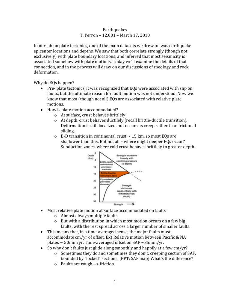
How is plate motion accommodated? o At surface, crust behaves brittlely o At depth, crust behaves ductilely (recall brittle-ductile transition).
Deformation is still localized, but occurs as creep rather than frictional sliding. o B-D transition in continental crust ~ 15 km, so most EQs are shallower than this. But not all – where might deeper EQs occur?
Subduction zones, where cold crust behaves brittlely to greater depth.
Most relative plate motion at surface accommodated on faults o Almost always multiple faults o But with a distribution in which most motion occurs on a few big faults, with the rest spread across a larger number of smaller faults.
This means that, in a time-averaged sense, the major faults must accommodate cm/yr of offset. Ex) Relative motion between Pacific & NA plates ~ 50mm/yr. Time-averaged offset on SAF ~35mm/yr.
So why don’t faults just glide along smoothly and happily at a few cm/yr? o Sometimes they do and sometimes they don’t: creeping section of SAF, bounded by “locked” sections. [PPT: SAF map] What’s the difference? o Faults are rough --> friction
1
o Static and dynamic friction forces can differ. The first-order explanation is that creeping faults have f d
> f s
, whereas faults that exhibit stick-slip behavior have f d
< f s
. [DEMO: friction block attached to spring] o What would make f d
> f s
, such that faults creep? A big research question. Probably lowering of static friction due to reduced normal stress or increased fluid pressure.
What controls when an EQ happens (i.e., when faults suddenly unlock)?
As plates move WRT one another, rocks deform elastically. o The displacement field asymptotically approaches (relative plate velocity)/2*(time) with perpendicular distance away from boundary o Displacement must go to zero at the boundary. For the simple case of a transform boundary, the displacement field is similar to the shape of an arctan curve (though the solution is not actually an arctan).
This elastic deformation must be caused by the buildup of stress (recall
Hooke’s law). Eventually, this stress will exceed the frictional strength of a fault within the plate boundary zone, and the fault will begin to slip.
Slip occurs along a finite section of the fault, releasing the energy stored in the elastic strain.
This hypothesized cycle of repeated buildup of stress, accumulation of distributed elastic strain, and rapid release of the energy stored in that elastic strain, has been labeled the EQ cycle.
2
o Does it really work this way? Obviously, not exactly: if it did, we’d be able to predict EQs. o There are some places that are close: we know that some faults repeatedly cause EQs with a characteristic size and recurrence interval. Ex) SAF near Parkfield, site of drilling project. o This is how most probabilistic attempts at EQ hazard forecasting work. [PPT: USGS “forecast” for SF Bay Area] o But in reality, there are several factors that prevent us from predicting
EQs this way:
Change in rate of stress accumulation (variations in plate motion) – add a curved line to the sketch
Incomplete stress release
Change in fault strength (rock WX, water pressure, “damage” due to previous EQs)
Changes in stress state due to nearby EQs
The actual EQ time series often looks like this:
What happens during an EQ?
Fault rupture nucleates at a point (focus or hypocenter). These are the first seismic waves emitted.
Rupture propagates outward along the fault surface at a few km/s (~ speed of sound in rock), continuing to emit seismic waves. (Note, though, that much of the energy released goes into frictionally generated heat.)
In large EQs, rupture propagation lasts seconds to over a minute, rupture length can be 100s of km, and total slip can be meters.
3
Rupture stops when stress drops below fault strength, or when it encounters material that behaves ductilely rather than brittlely.
Why doesn’t rupture stop propagating immediately after it starts, dropping stress back just below the fault strength? Again, the first-order answer is because f d
< f s
. Otherwise it would be a creeping fault.
What happens after an EQ?
Aftershocks o Smaller than mainshock o Sections on fault that didn’t slip, or didn’t completely relieve stress, or where stress increased. How can an EQ increase stress?
Release of elastic strain alters stress on surrounding faults (example later).
There is evidence that this can trigger large nearby EQs in addition to small aftershocks
Seismic waves propagate…we’ll discuss this shortly.
How do we describe EQ size, sense of slip and stress release, etc?
Size o Richter Scale (1930s)
Log
10
scale of amplitude of surface ground motion (each
Richter unit is 10x the ground motion)
Each Richter unit corresponds to a ~32x (=10 1.5
) increase in energy
Mostly obsolete o Moment Magnitude
Seismic moment, M o
Proportional to rupture area A, displacement D, and rigidity . Rigidity has units of stress, so moment has units of force*displacement, or work.
If irregular area, must integrate
Moment magnitude, M w
= ⅔ log
10
M o
– 10.73
The w subscript stands for work
M o
is determined from modeling of seismograms
Constants chosen so M w
values correspond approximately to old Richter scale. As with Richter, each
M w
unit corresponds to 10 1.5
x more energy
4
Ex) Solve for M o
to get expression for relative energy release: M o
= 10 3/2(Mw + 10.73) . So ratio of M o
for two quakes is 10 3/2(Mw1 – Mw2) . o For Chile 2010 (M w
8.8) vs. Haiti 2010 (M w
7.0), the ratio is 10 3/2*1.8
=500. o For Chile 1960 (M w
9.5) vs. Chile 2010 (M w
8.8) the ratio is 10 3/2*0.7
=11.
Use of logarithmic scales is efficient for science, bad for PR
(M9.5 doesn’t sound that much worse than a M7) o Mercalli intensity
Written in Roman numeral
Qualitative measure of severity based on observed effects on humans & structures
Source of estimates of EQ location & magnitude prior to seismometers
Sense of slip o Slip on a finite rupture creates zones of compression and zones of dilatation o This pattern will dictate the sense of first motion at seismic stations in the different zones. o The fault displacement in an EQ is constrained by examining the seismograms (including, but not limited to, first arrivals) at multiple stations, and determining the best-fit solution (“focal mechanism solution”) o To describe the pattern of energy radiated during an EQ (which is a tensor called the “moment tensor solution”), we use stereonets
(“beachballs”)
Take the intersection of the fault with a lower hemispherical surface centered on the focus
Mark the quadrants of compression and dilatation
Project the result onto a horizontal plane
5
Note that there is an ambiguity in the sense of slip. This is not just a limitation of the stereonet; it is a real limitation of our ability to determine the fault motion.
Examples from recent quakes: o Sumatra 2004
M w
= 9.0
[PPT: Moment tensor]
Dimensions: ~200km in dip dir, 1500 km in strike dir (about the size of California), max ~20m slip o Haiti 2010
M w
= 7.0
[PPT: Moment tensor]
Dimensions: ~15km x 40 km, max ~5 m / avg 2m slip
Enriquillo fault last ruptured on October 18 and November 21,
1751, and June 3, 1770
[PPT: Stress change on nearby Septentrional fault] o Chile 2010
M w
= 8.8
[PPT: Moment tensor]
Dimensions: ~50km x 400 km, max ~12 m / avg 7m slip o Chile 1960
M w
= 9.5 (largest EQ recorded w/modern instruments)
Dimensions: 1000 km along strike, max ~40m slip
Mw8.2 foreshock(!) 25 hrs before main shock, aftershocks as large as Mw7.9!
Seismic waves: 2 classes
Body waves o Compressional waves (P-waves)
Particle displacement parallel to propagation direction
Faster (P= “primary”)
V
P
= [(K + 4/3µ)/ρ] 1/2 , where µ is shear modulus (ratio of shear stress to shear strain), K is bulk modulus (“incompressibility”,
6
ratio of pressure change to volume change), and ρ is density.
Typical crustal V
P
~ 6 km/s
In liquid, µ 0, and V
P
= [K/ρ] 1/2 o Shear waves (S-waves)
Particle displacement normal to propagation direction
Slower (S = “secondary”)
V
S
= (µ/ρ) 1/2 . Typical crustal V
S
~3-4 km/s
In liquid, µ 0, and V
S
= 0
Surface waves o Slower than body waves (~3 km/s), but more destructive o [PPT: animations of surface waves] o Rayleigh waves
“Rolling” motion
Particle paths are elliptical in plane normal to surface and parallel to propagation direction o Love waves
Sideways shaking motion
Particle displacements are in the surface plane, normal to propagation direction. Essentially a horizontally polarized shear wave guided by the surface.
Slightly faster than Rayleigh waves
[PPT: Love waves in 1995 Kobe EQ]
Why are there variations in K, µ, ρ? o Mineral composition o Mineral phase (even for same elemental composition, crystal structure changes with P and T) o State of matter: Solid, liquid (melt), or a combination o Fabric: in this case, orientation of crystals o Stress state (you will explore this effect in your lab!) o These are all things that seismologists try to infer about the Earth, based on their observations of wave propagation
Wave propagation and arrival patterns o Surface waves travel along the surface. What path will body waves follow through Earth’s interior?
[Start drawing hypothetical ray paths on board] Depends on how wave speed varies with depth, because changes in speed will cause refraction.
7
What controls wave speed? Moduli and density.
How does density vary with depth? Increases slower speed!
What kind of ray paths would this predict?
How do moduli vary with depth? Not as easy to intuit…you will discover this in your lab. o Typical seismogram:
Interior Earth structure worked out by seismologists in early 20th c.: crust, mantle, outer & inner core. How? o Velocity of a medium + path of wave --> travel time o Differences in velocity between layers cause refraction, which also influences when (or even whether or not) a wave arrives at a given location
Ex) Liquid outer core inferred from “shadow zone” caused by gap between wave that just misses outer core, and refraction of wave that hits it. o Differences in velocity can also cause reflection
Ex) Inner core was originally suggested because there were actually some weak P-wave arrivals in shadow zones, which could be explained by a solid reflector inside the core. (Solid inner core was later demonstrated based on free oscillations.)
Other earthquake-related topics, time permitting
Change in MOI due to EQs (especially when dense subducting slabs move deeper into the mantle), TPW, and length-of-day
Earthquake hazards mitigation o Difference between impact of Haiti 2010 and Chile 2010 EQs o Use this to illustrate the difference between hazard and risk
8
