Article - I
advertisement
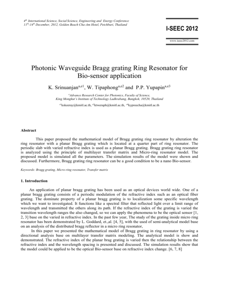
4th International Science, Social Science, Engineering and Energy Conference 11th-14th December, 2012, Golden Beach Cha-Am Hotel, Petchburi, Thailand I-SEEC 2012 www.iseec2012.com Photonic Waveguide Bragg grating Ring Resonator for Bio-sensor application K. Srinuanjana,e1, W. Tipaphonga,e2 and P.P. Yupapina,e3 a Advance Research Center for Photonics, Faculty of Science, King Mongkut’s Institute of Technology Ladkrabang, Bangkok, 10520, Thailand e1 kskeeray@kmitl.ac.th, e2ktweraph@kmitl.ac.th, e4kypreecha@kmitl.ac.th Abstract This paper proposed the mathematical model of Bragg grating ring resonator by alteration the ring resonator with a planar Bragg grating which is located at a quarter part of ring resonator. The periodic slab with varied refractive index is used as a planar Bragg grating. Bragg grating ring resonator is analyzed using the principle of multilayer transfer matrix and Micro-ring resonator model. The proposed model is simulated all the parameters. The simulation results of the model were shown and discussed. Furthermore, Bragg grating ring resonator can be a good condition to be a nano Bio-sensor. Keywords: Bragg grating, Micro-ring resonator, Transfer matrix 1. Introduction An application of planar bragg grating has been used as an optical devices world wide. One of a planar bragg grating consists of a periodic modulation of the refractive index such as an optical fiber grating. The dominate property of a planar bragg grating is to localization some specific wavelength which we want to investigated. It functions like a spectral filter that reflected light over a limit range of wavelength and transmitted the others along its path. If the refractive index of the grating is varied the transition wavelength ranges the also changed, so we can apply the phenomena to be the optical sensor [1, 2, 3] base on the varied in refractive index. In the past few year, The study of the grating inside micro ring resonator has been demonstrated by L. Goddard, et.,al. [4, 5], with the used of semi-analytical model base on an analysis of the distributed bragg reflector in a micro ring resonator, In this paper we presented the mathematical model of Bragg grating in ring resonator by using a directional analysis base on multilayer transfer matrix modeling. The analytical model is show and demonstrated. The refractive index of the planar brag grating is varied then the relationship between the refractive index and the wavelength spacing is presented and discussed. The simulation results show that the model could be applied to be the optical Bio-sensor base on refractive index change. [6, 7, 8] 2 Author name / Procedia Engineering 00 (2011) 000–000 2. Mathematical Model The mathematical model of Bragg grating ring resonator consist of two parts one is a general ring resonator and the second part is a periodic layers planar bragg grating located at a quarter part of the ring resonator waveguide which is function as a sensing region. For the mathematical modeling, we analysis each structure separately and then recombined it together for the whole system and the schematical diagram is show in figure 1 First part, the ring resonator, we apply the optical field (Ein) of Gaussian pulse into the model. The operating wavelength () range is set between 0.500 – 3.000 m and the center wavelength (0) is 1.550 m, which is defined by Ein A0e 1 0 2 /T02 2 (1) where A0 is amplitude of the optical field is applied into the ring and T 0 is the full wide at half max of the optical field. The optical field changes with distance, which is defined by L/4 E1G E2G Sensing Region Ein E2 E1 Eout Figure 1.The schematic diagram of Bragg grating ring resonator. Eout 1 1 E 1 i 1 E1G E1e i 1 Ein 1 1 E2 3L 3L jkn 8 8 (2) (3) Author name / Procedia Engineering 00 (2011) 000–000 E2G M T E1G E2 E2G e 3 (4) 3L 3L jkn 8 8 (5) where E1 is the optical field is coupler into the ring, is the fractional coupler intensity loss, is the coupling coefficient and E1G is the field before entering to bragg grating, L = 2R is the waveguide length, is an attenuation and kn = 2/ is the wave propagation number in vacuum. After that the optical field propagates into the bragg grating, the optical field is calculated by the multilayer transfer matrix, where E2G is the optical field leaves of the bragg grating. Then the optical field is in the form of M T E1G ,Where M T is the transfer matrix of multilayer and Eout is the optical field leaves of the ring. In the second part, the periodic high-low layers of refractive index, functional as the planar bragg grating, the multilayer transfer matrix is used for mathematical analysis. The relate of the optical field at boundary of layer in bragg grating could be written in the form of matrix equation. The transfer function of the planar bragg grating is the combination of high-low layer (nL and nH) refractive index matrix representation, which is defined by M T M H M L M H M L ... M H (6) where MT is transfer function matrix, MH and ML are the transfer high(nH) and low(nL) refractive index matrix which is defined by cos H M H i sin H H where H 2 0 H nH 0 0 nH t and and L i sin H H cos H i sin L cos L L ML i sin cos L L L 2 L n t , t is the thickness of 0 L (7) (8) periodic layer in bragg grating. nL 0 0 , 0 and 0 is permittivity and permeability in free space. The normalized output of the light field is the ratio between the output and input field which is defined by Eout Ein 1 1 1 M T Z12 1 1 1 M T Z12 (9) 4 Author name / Procedia Engineering 00 (2011) 000–000 Eout Ein 2 1 1 1 M T Z12 1 1 1 M T Z12 2 (10) 3L 3L jkn 8 8 Where Eout and Ein is the optical field leave and enter to the ring and Z1 = e . For the mathematical model simulation, The value of each parameters simulation is used as follows, the refractive index of ring resonator n0 = 3.34. (The material is InGaAsP/InP ) which the length of the ring L= 3.10 m. LB is the length of bragg grating which located at a quarter part of ring resonator, LB = L/4. The bragg grating consists of the periodic high-low refractive index, 17 multilayers. High refractive index (nH) is 3.34 and the low refractive index (nL) is varied, from 1.20 – 1.80, i.e optical Biosensor region. The wavelength of bragg grating reflection is defined by the relationship, B = 2neff where neff provides the effective index and is the period of the grating. The simulation result is plotted and show in Figure 2. 3. Simulation and discussion The simulation results of the mathematical model with periodic refractive index for 17 layers of bragg grating is show in Figure 2. The high refractive index of nH is set as 3.34. The relationship between Intensity and Wavelength is show and indicates that (a) when the refractive index of nL is 1.30, the wavelength spacing is 0.407 m. (b) when the refractive index of nL is 1.40, the wavelength spacing is 0.384 m. (c) when the refractive index of nL is 1.50, the wavelength spacing is 0.359 m. (d) when the refractive index of nL is 1.60, the wavelength spacing is 0.335 m. (e) when the refractive index of nL is 1.70, the wavelength spacing is 0.312 m. and (f) when the refractive index of nL is 1.80, the wavelength spacing is 0.292 m. 17 layers , nL = 1.30 0.7 D=0.407 m 0.6 0.5 0.5 Intensity (a.u.) Intensity (a.u.) 0.6 0.4 0.3 0.2 D=0.384 m 0.4 0.3 0.2 0.1 0.1 0 0.5 17 layers , nL = 1.40 0.7 1.0 1.5 2.0 Wavelength (m) (a) 2.5 3.0 0 0.5 1.0 1.5 2.0 Wavelength (m) (b) 2.5 3.0 Author name / Procedia Engineering 00 (2011) 000–000 0.7 D=0.359 m 0.6 0.6 0.5 0.5 Intensity (a.u.) Intensity (a.u.) 17 layers , nL = 1.60 17 layers , nL = 1.50 0.7 0.4 0.3 0.3 0.2 0.1 0.1 0.5 1.0 2.0 1.5 Wavelength (m) 2.5 0 3.0 D=0.335 m 0.4 0.2 0 0.5 1.0 1.5 2.5 3.0 (d) 17 layers , nL = 1.70 17 layers , nL = 1.80 0.7 D=0.312 m 0.6 0.5 0.5 Intensity (a.u.) Intensity (a.u.) 0.6 0.4 0.3 0.2 D=0.292 m 0.4 0.3 0.2 0.1 0.1 0 2.0 Wavelength (m) (c) 0.7 5 0.5 1.0 1.5 2.0 Wavelength (m) (e) 2.5 3.0 0 0.5 1.0 1.5 2.0 Wavelength (m) 2.5 3.0 (f) Figure 2.The relationship between Intensity and wavelength, the refractive index is varied in as followed, (a) the refractive index nL is 1.30, the wavelength spacing is 0.407 m. (b) the refractive index nL is 1.40, the wavelength spacing is 0.384 m. (c) the refractive index nL is 1.50, the wavelength spacing is 0.359 m. (d) the refractive index nL is 1.60, the wavelength spacing is 0.335 m. (e) the refractive index nL is 1.70, the wavelength spacing is 0.312 m. ,and (f) the refractive index nL is 1.80, the wavelength spacing is 0.292 m. Figure3. Show the relationship between the refractive index and the wavelength spacing. The simulation results from Figure 2 presented the linear relationship between Intensity and Wavelength. When the low refractive index of nL is increased, the wavelength spacing is then decreased. 6 Author name / Procedia Engineering 00 (2011) 000–000 1.90 1.80 y = - 5.4191 x + 5.3813 R 2 = 0.9993 Refractive index 1.70 1.60 1.50 1.40 1.30 1.20 1.10 1.00 0.640 0.660 0.680 0.700 0.720 0.740 0.760 0.780 The wavelength spacing (m) Figure 3.The relationship between the refractive index and the wavelength spacing. 4. Conclusion In this paper we proposed the model of Bragg grating in ring resonator and its application. The mathematical model is then analyzed. The simulation results show that the relationship between the refractive index and the wavelength spacing for each parameter, varying in low refractive index of periodic layers , have the linearity relationship, the least square R2 = 0.9993 which approach unit. That mean it is a good sensing performance. This model can be application of the optical Bio-sensor device in the near future. References [1] Sunita Ugale, Dr. V. Mishra. Fiber Bragg Grating Modeling, Characterization and Optimization with different index profiles. International Journal of Engineering Science and Technology; Vol 2(9), 2010: 4463-4468. [2] Stephen J. Mihailov. Fiber Bragg Grating Sensors for Harsh Enviroments. Sensors 2012; 12: 1898-1918 [3] Ho Sze Phing, Jalil Ali, Rosly Abdul Rahman, Bashir Ahmed Thir. Fiber Bragg grating modeling, simulation and characterstics with different grating lenths. Journal of Fundamental Sciences 3; 2007: 167-175. [4] Young MoKang, AmirArbabi, Lynford L. Goddard. Engineering the spectral reflectance of Microring resonators with integrated reflective elements. Optics Express; Vol. 18, No 16, 2 August 2010: 16813-16825. [5] Young MoKang, AmirArbabi, Lynford L. Goddard. A microring resonator with an integrated Bragg grating: a compact replacement for a sampled grating distributed Bragg reflector. Opt Quant Electron; 2009: 689-697. [6] Agostino Iadicicco, Stefania Campopiano, Antonello Cutolo, Michele Giordano, Andrea Cusano. Refractive Index Sensor Based on Microstructured Fiber Bragg Grating. IEEE Photonics Technology Letters; Vol 17, No. 6, June 2005: 1250-1252. [7] Maiko Girschikofsky, Manuel Rosenberger, Stefan Belle, Malte Brutschy, Siegfried R. Waldvogel, Ralf Hellmann. Highly Sensitive Detection of Naphthalene in Solvent Vapor Using a Functionalized PBG Refractive Index Sensor. Sensors 2012; 12: 2018-2025. [8] Y L Jin, J Y Chen, L Xu, P N Wang. Refractive index measurement for biomaterial samples by total internal reflection. Phys. Med. Biol; 51, 2006: 371-379.

