Modern Drive Technology
advertisement

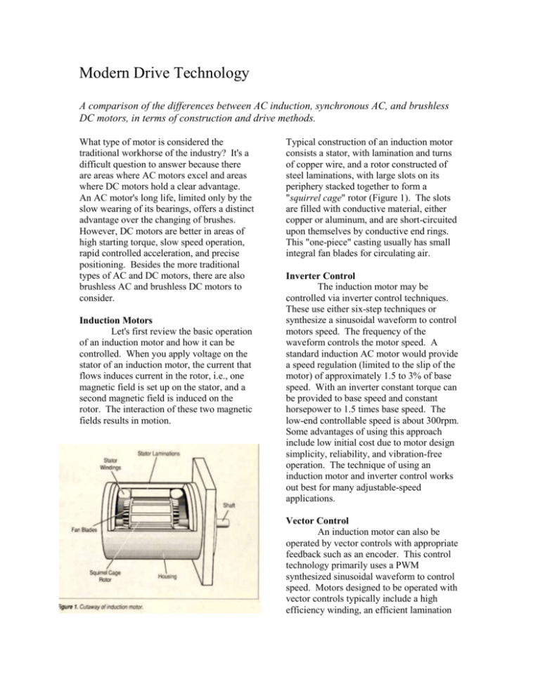
Modern Drive Technology A comparison of the differences between AC induction, synchronous AC, and brushless DC motors, in terms of construction and drive methods. What type of motor is considered the traditional workhorse of the industry? It's a difficult question to answer because there are areas where AC motors excel and areas where DC motors hold a clear advantage. An AC motor's long life, limited only by the slow wearing of its bearings, offers a distinct advantage over the changing of brushes. However, DC motors are better in areas of high starting torque, slow speed operation, rapid controlled acceleration, and precise positioning. Besides the more traditional types of AC and DC motors, there are also brushless AC and brushless DC motors to consider. Induction Motors Let's first review the basic operation of an induction motor and how it can be controlled. When you apply voltage on the stator of an induction motor, the current that flows induces current in the rotor, i.e., one magnetic field is set up on the stator, and a second magnetic field is induced on the rotor. The interaction of these two magnetic fields results in motion. Typical construction of an induction motor consists a stator, with lamination and turns of copper wire, and a rotor constructed of steel laminations, with large slots on its periphery stacked together to form a "squirrel cage" rotor (Figure 1). The slots are filled with conductive material, either copper or aluminum, and are short-circuited upon themselves by conductive end rings. This "one-piece" casting usually has small integral fan blades for circulating air. Inverter Control The induction motor may be controlled via inverter control techniques. These use either six-step techniques or synthesize a sinusoidal waveform to control motors speed. The frequency of the waveform controls the motor speed. A standard induction AC motor would provide a speed regulation (limited to the slip of the motor) of approximately 1.5 to 3% of base speed. With an inverter constant torque can be provided to base speed and constant horsepower to 1.5 times base speed. The low-end controllable speed is about 300rpm. Some advantages of using this approach include low initial cost due to motor design simplicity, reliability, and vibration-free operation. The technique of using an induction motor and inverter control works out best for many adjustable-speed applications. Vector Control An induction motor can also be operated by vector controls with appropriate feedback such as an encoder. This control technology primarily uses a PWM synthesized sinusoidal waveform to control speed. Motors designed to be operated with vector controls typically include a high efficiency winding, an efficient lamination design, and high-temperature insulation materials. With vector control, tighter speed regulation approaching 0.01% of set speed may be attained. A vector control allows controllable speed ranges from about 5 times base speed down to zero speed. The constant horsepower range is about 3.5 times the base speed. Smooth stopping and highly efficient operation may be attained by using a vector control. A standard vector control with dynamic brake (D.B) resistor may be used in many applications. Whenever a motor is stopped faster than if it were coasting to a stop, it becomes a greater generator. The energy or power generated by the motor may be shunted through the external D.B. resistor and dissipated as heat. However, if the application has high inertial loads, consider a line regeneration ("line regen") vector control. The energy or power generated by the motor is put back onto the incoming power line (Figure 2). "Line Regen" controls save energy back to the power line. Additionally, these designs operate near unity power factor, so they provide additional energy savings. Advantages of this approach include low initial cost, reliability, the capability of providing full rated torque from rated speed down to zero speed, precise speed and torque control, constant horsepower output above rated speed, and such programmable features as controlling acceleration/deceleration time and tuning. Induction motors with vector controls can be applied in high-performance adjustable-speed applications. For positioning applications, they can be used with proper position controllers. Synchronous Motors A synchronous motor is like an induction motor with a slightly different rotor. The rotor construction enables this type of motor rotate at the same speed, in synchronization as the stator field. There are two kinds of synchronous motors: self excited (as the induction motor) and directly exited (as with permanent magnets). The self-excited -or reluctance synchronous-motor has a rotor with notches, flats or teeth on the periphery (Figure 3). These teeth are also called salient poles. They create an easy path for the magnetic field to follow, thus allowing the rotor to lock "lock in" and run at the same speed as the rotating field. During operation the rotor lags a small distance behind the stator field. This increases with load; and if the load is increased beyond the motor's capability the rotor "pulls out" of synchronism. Brushless Motors When a synchronous motor is excited directly, as with permanent magnets, it is called a brushless motor. The rotor is a cylinder of permanent magnet alloy; such materials as ferrite, samarium cobalt or neodymium can be used. The north/south poles are, in effect, the design's salient teeth and prevent the motor from slipping. Brushless motors are driven by selectively applying power onto their windings. In order to know when to apply power, some type of rotor position feedback, such as Hall sensors, encoders or resolvers, must be used. Informing the control when to switch power from winding to winding is called electronic communication. Brushless Controls When driving a three-phase brushless motor by energizing two of the three windings at a time, simple Hall sensor feedback can be used. Because there are six different commutation sections in a threephase motor, this control scheme is referred to as six-step commutation. Some manufacturers use the term "DC" and, thus, call their drives "DC brushless." When sinusoidal waveform is applied to the motor windings on a continuous basis, the terms "AC brushless" is used. The motor has a three-phase sinusoidal back EMF and is being powered by a three-phase driving current waveform, so "extra torque" is available. Or rephrasing, for the same torque (compared to a "DC brushless" drive), the "AC brushless" drive will require less current. For this reason the AC brushless packages are popular (Figure 4). In addition, it may be possible to use a smaller size motor. This control scheme reduces torque ripple and provides good low speed operating conditions. Brushless motors are designed to provide an optimized-torque-per-package size and improve the torque-to-inertia ratio. They also offer rapid incrementing and accurate positioning. Inverter controls are presently available through 500hp. This technology works adequately in open loop adjustable speed applications. Table 1 compares the various closed loop drive technologies. Vector drives are available up through 500hp. These can be used in adjustable speed application for improved speed control, or in a positioning application. Commercially available brushless drives typically range through 15hp, custom designs are range to 60hp, and specialty designs provide higher horsepower. The advantage of brushless servos would be the rapid positioning capability in a smaller package size. For proper sizing and selection, acceleration torque, package size and inertia matching, all should be considered when selecting a drive package for the application.


