AIM - Physics - University of Surrey
advertisement
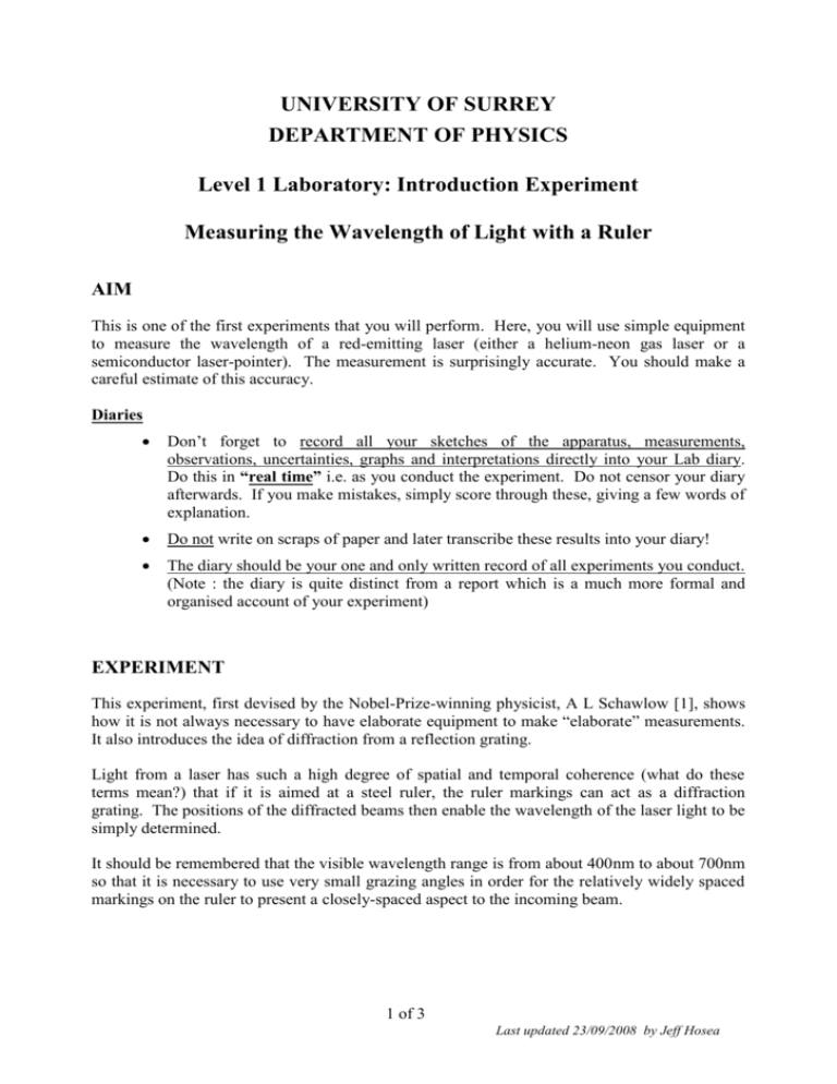
UNIVERSITY OF SURREY DEPARTMENT OF PHYSICS Level 1 Laboratory: Introduction Experiment Measuring the Wavelength of Light with a Ruler AIM This is one of the first experiments that you will perform. Here, you will use simple equipment to measure the wavelength of a red-emitting laser (either a helium-neon gas laser or a semiconductor laser-pointer). The measurement is surprisingly accurate. You should make a careful estimate of this accuracy. Diaries Don’t forget to record all your sketches of the apparatus, measurements, observations, uncertainties, graphs and interpretations directly into your Lab diary. Do this in “real time” i.e. as you conduct the experiment. Do not censor your diary afterwards. If you make mistakes, simply score through these, giving a few words of explanation. Do not write on scraps of paper and later transcribe these results into your diary! The diary should be your one and only written record of all experiments you conduct. (Note : the diary is quite distinct from a report which is a much more formal and organised account of your experiment) EXPERIMENT This experiment, first devised by the Nobel-Prize-winning physicist, A L Schawlow [1], shows how it is not always necessary to have elaborate equipment to make “elaborate” measurements. It also introduces the idea of diffraction from a reflection grating. Light from a laser has such a high degree of spatial and temporal coherence (what do these terms mean?) that if it is aimed at a steel ruler, the ruler markings can act as a diffraction grating. The positions of the diffracted beams then enable the wavelength of the laser light to be simply determined. It should be remembered that the visible wavelength range is from about 400nm to about 700nm so that it is necessary to use very small grazing angles in order for the relatively widely spaced markings on the ruler to present a closely-spaced aspect to the incoming beam. 1 of 3 Last updated 23/09/2008 by Jeff Hosea Safety Notice The laser pointer contains an intense light source. Do not stare into the beam. Be mindful of the safety of others by always pointing the laser towards the screen and making sure that reflections from shiny surfaces are stopped by the screen INITIAL SETTING UP Set up the equipment as shown in Fig. 1 below. y2 lase 2 ruler y0 specular ray 0 Figure 1 : y1 diffracted rays r x Schematic of the apparatus for observing laser diffraction from a steel ruler. The angle 0 refers to the specularly-reflected beam, so that 0 = the incidence angle, . In Equ.(1) below, the angle of diffraction of the nth diffracted beam is defined as n. The figure shows an example angle of diffraction, 2 , for the 2nd diffracted ray. Adjust the ruler so that the beam impinges on the finest (metric) scale. The steel ruler markings act as a reflection grating, producing a series of bright spots on the vertical board. The distance to the board, x, and the height of the spots, y, can be measured with a metre rule. Note that the spot heights y are measured from the height corresponding to level of the ruler surface, which is above the bench top. In order to find which spot corresponds to the specular reflection (y0), shift the ruler sideways slightly so that the beam impinges on an unmarked portion. Note that the specular spot corresponding to y0 may not be the lowest spot you observe. THEORY The incidence angle and the diffraction angle n satisfy the grating equation : n = d(sin - sin n) (1) where d is the grating spacing, n the diffraction order and the wavelength of the laser light. Now, from simple geometry 2 of 3 Last updated 23/09/2008 by Jeff Hosea sin n x x 2 y n2 1 . (2) 2 where yn is the height of the nth diffracted spot. Provided the spot heights are small compared to the distance to the vertical board, i.e. yn << x, Equ. (2) may be approximated by : sin n 1 y n2 2x 2 (3) Therefore, from Equ. (1), and the fact that = 0 , we finally have : n d 2 yn2 y02 2x 2 2 2 n . or y y n 0 2 d x (4) PROCEDURE Plot a graph of y n2 against the order of diffraction n. Determine the gradient and the uncertainty in the gradient (you may use the parallelogram method here). The gradient equals 2x2/d so from this you can calculate the wavelength of the laser . In addition to the uncertainty in the gradient, there are uncertainties in x and d. How do these combine to give the overall uncertainty in ? Which contribution is largest and which is smallest? Compare your final result with the expected value for the laser wavelength. If time permits, investigate qualitatively the effect of changing the laser light incident angle and the rule scale. Account for your observations. References [1] A. L. Schawlow, American Journal of Physics 33 922 (1965) 3 of 3 Last updated 23/09/2008 by Jeff Hosea


