DC Circuits TAG Rubric - Ohio College Tech Prep
advertisement

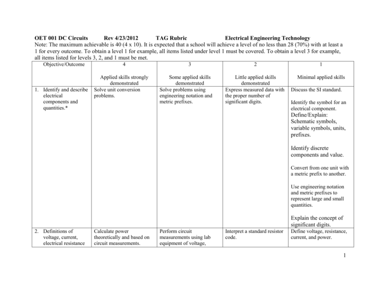
OET 001 DC Circuits Rev 4/23/2012 TAG Rubric Electrical Engineering Technology Note: The maximum achievable is 40 (4 x 10). It is expected that a school will achieve a level of no less than 28 (70%) with at least a 1 for every outcome. To obtain a level 1 for example, all items listed under level 1 must be covered. To obtain a level 3 for example, all items listed for levels 3, 2, and 1 must be met. Objective/Outcome 1. Identify and describe electrical components and quantities.* 4 Applied skills strongly demonstrated Solve unit conversion problems. 3 Some applied skills demonstrated Solve problems using engineering notation and metric prefixes. 2 1 Little applied skills demonstrated Express measured data with the proper number of significant digits. Minimal applied skills Discuss the SI standard. Identify the symbol for an electrical component. Define/Explain: Schematic symbols, variable symbols, units, prefixes. Identify discrete components and value. Convert from one unit with a metric prefix to another. Use engineering notation and metric prefixes to represent large and small quantities. Explain the concept of significant digits. 2. Definitions of voltage, current, electrical resistance Calculate power theoretically and based on circuit measurements. Perform circuit measurements using lab equipment of voltage, Interpret a standard resistor code. Define voltage, resistance, current, and power. 1 and power.* 3. Ohm’s law, electrical energy and power.* 4. Series circuit analysis (Apply Ohm’s and Kirchhoff’s Laws to series circuits.)* current and resistance. Describe the relationship between voltage current and resistance. Discuss the characteristics of power supplies and batteries. Calculate current, voltage and resistance in a simple circuit. Measure voltage current and resistance in a simple circuit. Calculate electrical power and energy for a simple circuit. Define electrical power. Calculate energy consumption. Select resistors based on power considerations. Apply the voltage divider rule. Calculate electrical power for a basic circuit. Compute DC series circuits (voltages, current, power). Define series circuit Design, build and test an unloaded voltage divider circuit. Take measurements of DC series circuits. Recognize series combinations of components from schematic diagrams. Design, build and test a circuit to achieve a specific current, resistance or voltage. Construct a circuit and measure voltage with respect to ground. Troubleshoot series circuits, opens and shorts. Construct and analyze series-aiding and seriesopposing multiple source circuits. Compute power in and power out. Apply Kirchhoff’s Voltage Law. Verify current is the same through all components. Define Ohm’s law. Define electrical energy. State Kirchhoff’s Voltage law. Apply Ohm’s Law in a series circuit to each component and combination of components. Recognize series-aiding and series-opposing multiple source circuits. Compute voltages in seriesaiding and series-opposing multiple source circuits. 2 5. Parallel circuit analysis* Apply the current divider rule Design, build, and test a current divider circuit. Construct a circuit and measure voltage with respect to ground. Troubleshoot parallel circuits, opens and shorts. Construct and analyze parallel multiple source circuits. Analyze the internal resistance of single and multiple source circuits. 6. Series-parallel circuit analysis* Analyze by calculation using the collapse and expand method for a 3 plus loop circuit. Compute DC parallel Recognize parallel circuits (voltages, current, combinations of power). components from schematic diagrams. Take measurements of DC parallel circuits. Determine total parallel resistance with three or more resistors. Compute power in and power out. Apply Kirchhoff’s Current Law to solve a simple circuit. Verify voltage is the same across all parallel components. Define parallel circuit State Kirchhoff’s Current law Determine total parallel resistance with two resistors in parallel. Apply Ohm’s Law in a parallel circuit to each component and combination of components. Recognize parallel multiple source circuits. Compute current in a parallel multiple source circuit. Analyze by calculation using the collapse and expand method for a 2 loop circuit. Determine total Recognize series-parallel equivalent resistance for a circuits. series-parallel circuit. Recognize a ladder network. Analyze using simulation. Analyze ladder networks. Design, build, and test a loaded voltage divider. Analyze a balanced Wheatstone bridge. Recognize a balanced Wheatstone bridge. Analyze the loading effect of a meter on a 3 circuit. 7. Circuit theorems (Superposition, Thevenin’s and Norton’s theorems)* Lab exercise or computer simulation to prove Thevenin and/or Norton theorem. Lab exercise or computer simulation to prove Superposition theorem. Lab exercise or computer simulation to prove Maximum Power Transfer theorem. 8. Mesh and/or nodal analysis techniques* Apply Mesh or Nodal Analysis Techniques to find currents through and voltage drops across all resistors in a complex circuit (three or more loops). Lab exercise or computer simulation to validate Mesh or Nodal analysis 9. Properties of capacitors and their behavior under DC Verify results by applying Kirchhoff’s Laws. Apply and verify the universal time constant curve in an R-C circuit. Calculate the equivalent Thevenin and/or Norton circuit. Perform source conversions (current to voltage; voltage to current). Define the concept of equivalent circuits and internal resistance. Convert a Norton circuit to a Thevenin circuit and Thevenin circuit to Norton circuit. Calculate the voltages and current in a multi-source series-parallel circuit. Define superposition, Thevenin’s, and Norton’s theorems. Define Maximum Power Transfer theorem. Calculate circuit voltages & currents using Superposition. Calculate resistances for Maximum Power Transfer. Apply Mesh or Nodal Analysis Techniques to find currents through and voltage drops across all resistors in a simple circuit (two loops). Write Mesh equations for a simple circuit with two loops or write nodal equations for a simple circuit with two nodes. Verify results by applying Kirchhoff’s Laws. Recognize when source conversion is necessary and perform source conversion. Analyze series and parallel connections of capacitors Describe dielectric characteristics Calculate capacitance from Describe voltage and Describe the procedure used in the Mesh or Nodal Analysis Techniques. Recognize which of Kirchhoff’s Laws are being applied in each analysis technique. Define capacitance Describe basic construction and characteristics of a 4 conditions* Observe R-C transient circuits with instrumentation. Solve for voltage, current, and time in an RC circuit using exponential equations. physical characteristics of a capacitor. Perform calculations using the universal time constant curve. Calculate energy stored in a capacitor Calculate the Voltage and Current in an R-C circuit at and 5 10. Properties of inductors and their behavior under DC conditions* Apply and verify the universal time constant curve in an R-L circuit. Observe R-L transient circuits with instrumentation. Solve for voltage, current, and time in an R-L circuit using exponential equations. Calculate mutual inductance. Analyze series and parallel connections of inductors. current in steady state condition of an R-C circuit. capacitor Identify and discuss various Describe/plot current and types of capacitors voltage in a transient circuit. Define charge, charge Calculate charge on a storage, and discuss voltage capacitor. as force. Describe energy stored in a capacitor Calculate time constant of an R-C circuit Describe voltage and current in steady state condition of an R-L circuit. Calculate inductance from physical characteristics of an inductor. Describe/plot current and voltage in a transient circuit. Perform calculations using the universal time constant curve. Calculate induced voltage during a collapsing magnetic field. Calculate energy stored in an inductor. Describe energy stored in an inductor. Calculate the Voltage and Current in an R-L circuit at and 5 Calculate the time constant of an R-L circuit. Identify and discuss the universal time constant curve Define inductance. Define the basic construction of an inductor. Identify and discuss various types of inductors. List the factors that affect the strength of the magnetic field. Identify and discuss the universal time constant curve. 5


