3-130 The inner and outer surfaces of a long thick-walled
advertisement
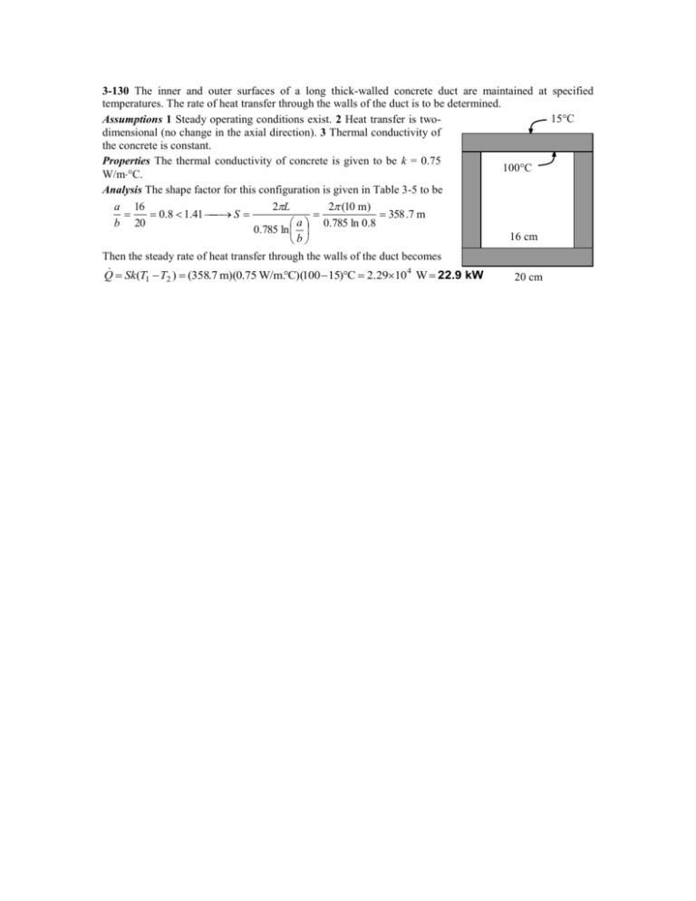
3-130 The inner and outer surfaces of a long thick-walled concrete duct are maintained at specified temperatures. The rate of heat transfer through the walls of the duct is to be determined. 15C Assumptions 1 Steady operating conditions exist. 2 Heat transfer is twodimensional (no change in the axial direction). 3 Thermal conductivity of the concrete is constant. Properties The thermal conductivity of concrete is given to be k = 0.75 100C W/m°C. Analysis The shape factor for this configuration is given in Table 3-5 to be a 16 0.8 1.41 S b 20 2L 2 (10 m) 358 .7 m a 0.785 ln 0.8 0.785 ln b Then the steady rate of heat transfer through the walls of the duct becomes Q Sk (T T ) (358.7 m)(0.75 W/m.C)(100 15)C 2.2910 4 W 22.9 kW 1 2 16 cm 20 cm 3-132 "!PROBLEM 3-132" "GIVEN" "D=3 [m], parameter to be varied" k=1.4 "[W/m-C]" h=4 "[m]" T_1=140 "[C]" T_2=15 "[C]" "ANALYSIS" z=h+D/2 S=(2*pi*D)/(1-0.25*D/z) Q_dot=S*k*(T_1-T_2) D [m] 0.5 1 1.5 2 2.5 3 3.5 4 4.5 5 Q [W] 566.4 1164 1791 2443 3120 3820 4539 5278 6034 6807 7000 6000 Q [W] 5000 4000 3000 2000 1000 0 0.5 1 1.5 2 2.5 3 D [m] 3.5 4 4.5 5 3-139 The R-value and the U-factor of a wood frame wall are to be determined. Assumptions 1 Steady operating conditions exist. 2 Heat transfer through the wall is one-dimensional. 3 Thermal properties of the wall and the heat transfer coefficients are constant. Properties The R-values of different materials are given in Table 3-6. Analysis The schematic of the wall as well as the different elements used in its construction are shown below. Heat transfer through the insulation and through the studs will meet different resistances, and thus we need to analyze the thermal resistance for each path separately. Once the unit thermal resistances and the U-factors for the insulation and stud sections are available, the overall average thermal resistance for the entire wall can be determined from Roverall = 1/Uoverall where Uoverall = (Ufarea )insulation + (Ufarea )stud and the value of the area fraction farea is 0.80 for insulation section and 0.20 for stud section since the headers that constitute a small part of the wall are to be treated as studs. Using the available R-values from Table 3-6 and calculating others, the total R-values for each section is determined in the table below. 4b Construction 6 3 4a 5 1. Outside surface, 12 km/h wind 2. Wood bevel lapped siding 3. Fiberboard sheathing, 25 mm 4a. Mineral fiber insulation, 140 mm 4b. Wood stud, 38 mm by 140 mm 5. Gypsum wallboard, 13 mm 6. Inside surface, still air R-value, m2.C/W Between At studs studs 0.044 0.044 0.14 0.14 0.23 0.23 3.696 --0.98 0.079 0.079 0.12 0.12 1 Total unit thermal resistance of each section, R (in m2.C/W) The U-factor of each section, U = 1/R, in W/m2.C Area fraction of each section, farea Overall U-factor, U = farea,iUi = 0.800.232+0.200.628 Overall unit thermal resistance, R = 1/U 4.309 1.593 0.232 0.628 0.80 0.20 0.311 W/m2.C 3.213 m2.C/W Therefore, the R-value and U-factor of the wall are R = 3.213 m2.C/W and U = 0.311 W/m2.C. 3-140 The change in the R-value of a wood frame wall due to replacing fiberwood sheathing in the wall by rigid foam sheathing is to be determined. Assumptions 1 Steady operating conditions exist. 2 Heat transfer through the wall is one-dimensional. 3 Thermal properties of the wall and the heat transfer coefficients are constant. Properties The R-values of different materials are given in Table 3-6. Analysis The schematic of the wall as well as the different elements used in its construction are shown below. Heat transfer through the insulation and through the studs will meet different resistances, and thus we need to analyze the thermal resistance for each path separately. Once the unit thermal resistances and the U-factors for the insulation and stud sections are available, the overall average thermal resistance for the entire wall can be determined from Roverall = 1/Uoverall where Uoverall = (Ufarea )insulation + (Ufarea )stud and the value of the area fraction farea is 0.80 for insulation section and 0.20 for stud section since the headers that constitute a small part of the wall are to be treated as studs. Using the available R-values from Table 3-6 and calculating others, the total R-values for each section of the existing wall is determined in the table below. 4b Construction 6 3 1 4a 5 1. Outside surface, 12 km/h wind 2. Wood bevel lapped siding 3. Fiberboard sheathing, 25 mm 4a. Mineral fiber insulation, 140 mm 4b. Wood stud, 38 mm by 140 mm 5. Gypsum wallboard, 13 mm 6. Inside surface, still air R-value, m2.C/W Between At studs studs 0.044 0.044 0.14 0.14 0.23 0.23 3.696 --0.98 0.079 0.079 0.12 0.12 2 Total unit thermal resistance of each section, R (in m2.C/W) The U-factor of each section, U = 1/R, in W/m2.C Area fraction of each section, farea Overall U-factor, U = farea,iUi = 0.800.232+0.200.628 Overall unit thermal resistance, R = 1/U 4.309 1.593 0.232 0.628 0.80 0.20 0.311 W/m2.C 3.213 m2.C/W Therefore, the R-value of the existing wall is R = 3.213 m2.C/W. Noting that the R-values of the wood fiberboard and the rigid foam insulation are 0.23 m 2.C/W and 0.98 m2.C/W, respectively, and the added and removed thermal resistances are in series, the overall Rvalue of the wall after modification becomes Rnew Rold Rremoved Radded 3213 . 0.23 0.98 3963 . m2 . C / W Then the change in the R-value becomes %Change R value 3.963 3.213 0.189 R value, old 3.963 (or 18.9%) 3-141E The R-value and the U-factor of a masonry cavity wall are to be determined. Assumptions 1 Steady operating conditions exist. 2 Heat transfer through the wall is one-dimensional. 3 Thermal properties of the wall and the heat transfer coefficients are constant. Properties The R-values of different materials are given in Table 3-6. Analysis The schematic of the wall as well as the different elements used in its construction are shown below. Heat transfer through the air space and through the studs will meet different resistances, and thus we need to analyze the thermal resistance for each path separately. Once the unit thermal resistances and the U-factors for the air space and stud sections are available, the overall average thermal resistance for the entire wall can be determined from Roverall = 1/Uoverall where Uoverall = (Ufarea )air space + (Ufarea )stud and the value of the area fraction farea is 0.80 for air space and 0.20 for the ferrings and similar structures. Using the available R-values from Table 3-6 and calculating others, the total R-values for each section of the existing wall is determined in the table below. 5b Construction 6 5a 7 1. Outside surface, 15 mph wind 2. Face brick, 4 in 3. Cement mortar, 0.5 in 4. Concrete block, 4-in 5a. Air space, 3/4-in, nonreflective 5b. Nominal 1 3 vertical ferring 6. Gypsum wallboard, 0.5 in 7. Inside surface, still air R-value, h.ft2.F/Btu Between At furring furring 0.17 0.17 0.43 0.43 0.10 0.10 1.51 1.51 2.91 --0.94 0.45 0.45 0.68 0.68 4 1 2 3 Total unit thermal resistance of each section, R The U-factor of each section, U = 1/R, in Btu/h.ft2.F Area fraction of each section, farea Overall U-factor, U = farea,iUi = 0.800.160+0.200.234 Overall unit thermal resistance, R = 1/U 6.25 4.28 0.160 0.234 0.80 0.20 0.175 Btu/h.ft2.F 5.72 h.ft2.F/Btu Therefore, the overall unit thermal resistance of the wall is R = 5.72 h.ft2.F/Btu and the overall U-factor is U = 0.118 Btu/h.ft2.F. These values account for the effects of the vertical ferring.

