Module 24: Reactor Design Applied to a Solid Oxide Fuel Cell
advertisement
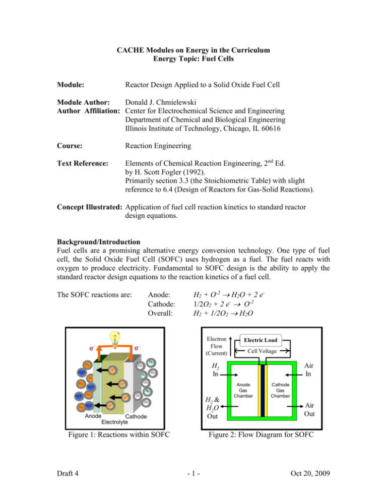
CACHE Modules on Energy in the Curriculum Energy Topic: Fuel Cells Module: Reactor Design Applied to a Solid Oxide Fuel Cell Module Author: Donald J. Chmielewski Author Affiliation: Center for Electrochemical Science and Engineering Department of Chemical and Biological Engineering Illinois Institute of Technology, Chicago, IL 60616 Course: Reaction Engineering Text Reference: Elements of Chemical Reaction Engineering, 2nd Ed. by H. Scott Fogler (1992). Primarily section 3.3 (the Stoichiometric Table) with slight reference to 6.4 (Design of Reactors for Gas-Solid Reactions). Concept Illustrated: Application of fuel cell reaction kinetics to standard reactor design equations. Background/Introduction Fuel cells are a promising alternative energy conversion technology. One type of fuel cell, the Solid Oxide Fuel Cell (SOFC) uses hydrogen as a fuel. The fuel reacts with oxygen to produce electricity. Fundamental to SOFC design is the ability to apply the standard reactor design equations to the reaction kinetics of a fuel cell. The SOFC reactions are: Anode: Cathode: Overall: Electron Flow (Current) - - e e N2 H2 O2 N2 H2 H2 O2 O2- H2O H2 H2 H2O O2O2- O2 H2 & H2O Out O2 Anode Cathode Electrolyte Figure 1: Reactions within SOFC Draft 4 Cell Voltage Air In Anode Gas Chamber Cathode Gas Chamber Fuel Cell N2 H2O Electric Load H2 In O2 O2- H2O H2 + O-2 H2O + 2 e1/2O2 + 2 e- O-2 H2 + 1/2O2 H2O Air Out Figure 2: Flow Diagram for SOFC -1- Oct 20, 2009 For each mole of hydrogen consumed, two moles of electrons are passed through the electric load. To convert electron flow, Faraday’s constant should be used ( F 96,485 coulombs/mole of electrons). The objective of a fuel cell is to deliver power to the load: Power = Current · Voltage. ( coulomb volt joule and joule / s watt ). The fuel cell obtains this power from the enthalpy released during the overall reaction H2 + 1/2O2 H2O; however, only a portion of this enthalpy can be converted to electric power, the remainder will appear as heat released by the reaction. This heat must be removed using the flowing gas streams. The performance of a fuel cell is typically communicated in terms of efficiency, defined as energy delivered to the load divided by the energy available from reaction. Problem Information In many cases, one can think of a fuel cell as a chemical reactor. The primary difference is that the rate of reaction term will be a bit more complicated than the kinetic expressions usually encountered in the chemical engineering literature. In this module we will use one such rate expression and illustrate its use within the standard reactor design equations. As indicated in the background section above, there is a proportional relation between reaction rate and fuel cell current. If we define ri as the generation rate of species i per unit area of the cell (typically with units of mole / s cm2) then: j rH 2 rH 2O 2rO 2 2F (1) where j is as current density (defined as total current per unit area of the cell). Then, current density is given by: jcell = (Ener - Ecell ) / Rint (2) where Ecell is the operating voltage of the cell and Rint = /is the area specific resistance (is ionic conductivity of the electrolyte (with units of cm-1ohm-1) and is the electrolyte thickness). The Nernst voltage is given by: E ner 1/ 2 RT PH 2 PO2 Eo ln 2 F PH 2O (3) where Eo = -ΔGºrxn / 2F, ΔGºrxn is the Gibbs free energy of the reaction H2 + ½ O2 H2O (evaluated at standard pressures and the operating temperature of the cell) and the Pi’s are the partial pressures at the reaction sites. By substituting Equations 2 and 3 into Equation 1, we arrive at the following compact expression for the reaction rate: Draft 4 -2- Oct 20, 2009 rH 2 P P1 / 2 E RT ln H 2 O2 o 2 F PH O 2 / 2 F E cell (4) In section 2.2 of Fogler (1992), the reactor design equations for per volume reaction rates are given as: CSTR: V FA, o X rA ( X ) X PFR: dX rA ( X ) 0 V FA,o Since the reaction rate for a fuel cell is given on a per area basis, the corresponding reactor design equations are determined to be: CSTR: Acell FH 2,o X rH 2 ( X ) X PFR: dX rH 2 ( X ) 0 Acell FH 2,o (See section 6.4 of Fogler (1992) for a similar development. For the PFR case, a cocurrent configuration was assumed with regard to the anode and cathode gas chambers.) Example Problem Statement: An SOFC is operated at atmospheric pressure and 973K with the following inlet molar flow rates (all in mole/s): FH2,o = 5.0 and FH2O,o = 0.5, FO2,o = 30 and FN2,o = 113. At 973K, ΔGºrxn = -194 kJ /mole of H2, ΔHºrxn = -248 kJ / mole of H2 and = 0.05 cm-1 ohm-1. The electrolyte thickness is 20m. and the cell is operated at 0.75 volts. Assume the fuel cell is configured as two CSTR gas chambers separated by the electrode / electrolyte assembly (similar to figure 2). 1) If a 90% conversion of H2 is desired, determine the required electrolyte area, Acell. 2) Using the cell area determined in part 1, determine the resulting H2 conversion if the cell voltage is changed to 0.8 volts. Draft 4 -3- Oct 20, 2009 Example Problem Solution: Part 1): Defining X as the conversion of H2 (moles reacted per mole fed), we can construct the following table using the overall reaction: H2 + 1/2O2 H2O. Table 1: Stoichiometric Table for Example Problem Species Feed rate to reactor (mole/s) Change in reactor (mole/s) Effluent rate from reactor (mole/s) Concentration (mole/m3) H2 FH2,o -FH2,oX FH2,o(1-X) FH2,o(1-X)/(a) H2O H2O FH2,o +FH2,o X FH2,o(H2O +X) FH2,o(H2O +X)/(a) Total Anode Gas FT,o(a) = FH2,o+ FH2O,o 0 FT(a) = FT,o(a) - O2 FO2,o = O2 FH2,o - 1 FH2,o X FH2,o(O2 - 1 X) FH2,o(O2 - 1 X)/(c) N2 FN2,o = N2 FH2,o 0 FH2,oN2 FH2,o N2 /(c) Total Cathode Gas FT,o(c) = FO2,o+ FN2,o - 1 FH2,o X FT(c) = FT,o(c) - 1 FH2,o X - FH2O,o = 2 2 2 2 2 where H2O = FH2O,o / FH2,o, O2 and N2 are similarly defined. To determine (a) and (c) (the volumetric flow rates exiting the anode and cathode chambers, respectively), we employ Equation 3-41 of Fogler (1992), once for each chamber: Draft 4 (a) (c) (a) o FT( a ) F (a) T ,o Po ( a ) P ( a ) T ( a ) T ( a ) o (a) o( a ) T T (a) o FT( c ) Po ( c ) T ( c ) ( c ) ( c ) ( c ) F P To T ,o (c) 1 FT ,o FH 2,o X T ( c ) (c) 2 ( c ) o FT(,co) To (c) o ( c ) F o( c ) 1 1 H 2,o X T 2 F ( c ) T ( c ) T ,o o -4- Oct 20, 2009 Now recall that the partial pressure of species i in chamber j is given by Pi = CiRT(j), where Ci is the concentration expression developed in the last column of table 1. Similarly, Pi,o = (Fi,o /o(j)) RTo(j) is the inlet partial pressure. The pressures of interest are: PH 2 C H 2 RT ( a ) FH 2,o (1 X ) (a) o PH 2O C H 2O RT ( a ) T (a) To (a) RT ( a ) FH 2,o ( H 2O X ) o( a ) T ( a ) To ( a ) RT FH 2,o (1 X ) (a) 1 X) 2 T ( c ) X ( c ) T o FH 2,o ( O 2 PO 2 C O 2 RT ( c ) o( c ) 1 1 FH 2,o 2 FT(,co) (a) o RTo (a) PH 2,o (1 X ) PH 2,o ( H 2O X ) RT ( c ) 1 PO 2,o O 2 ( O 2 1 X ) PO 2,o ( O 2 1 X ) X) ( c ) 2 2 2 RTo 1 F 1 FH 2,o O 2 xO 2 ,o X 1 1 H 2 , o X o( c ) 1 X (c) (c) 2 2 2 F F T ,o T ,o FH 2,o ( O 2 where xO2,0 is the mole fraction of O2 and the cathode inlet and Pi,o is the partial pressure of species i at the inlet. These can now be substituted into the previous reaction rate expression (Equation 4): P P1 / 2 E RT ln H 2 O2 o 2 F PH O 2 rH 2 ( X ) / 2 F Eo E cell 1/ 2 1/ 2 RT (1 X ) PO 2,o ( O 2 X / 2) ln E cell 2 F ( H 2O X ) O 2 xO 2,o X / 2 1 / 2 / 2 F (5) 1/ 2 1/ 2 194000 8.314 973 (1 X ) 0.21 (6 X / 2) ln 0.75 1/ 2 2 96485 2 96485 (0.1 X ) 6 0.21 X / 2 0.00002 / 5 2 96485 Draft 4 -5- Oct 20, 2009 Then evaluation of equation 5 at X = 0.9 gives 1.005 rH 2 ( X 0.9) 8.314 973 (1 0.9) 0.211 / 2 (6 0.9 / 2)1 / 2 ln 0.75 2 96485 (0.1 0.9) 6 0.21 0.9 / 21 / 2 0.00002 / 5 2 96485 0.1617 moles / m 2 s Finally, we combine with the CSTR design equation to find the required area. Acell FH 2,o X (6) rH 2 ( X ) 5 0.9 27.8 m 2 rH 2 (0.9) At this point we can also calculate the amount of power being produced. We start by determining current density: j rH 2 2 F 0.1617 2 96485 3.12 10 4 A / m 2 Then the total power is found to be Pcell = Ecell Icell = Ecell j Acell = 0.75 x 3.12x104 x 27.8 = 651 kW Part 2): If cell voltage is changed to 0.8 the resulting H2 conversion can be determined either graphically or via a numeric search. Graphical Method: A plot of Acell(X) for part 1) is given in figure 3 (the curve denoted as Ecell = 0.75). The solution of Acell = 27.8 m2 is found as the point corresponding to a conversion of 0.9. The second curve (Ecell = 0.8) was generated by changing Ecell in equation 5 and substitution into equation 6. Then based on the second curve, the conversion corresponding to an area of 27.8 m2 is found to be about 0.79. The following Matlab code was used to generate the plots of figure 3. clear FH2o=5.0; FH2Oo=0.5; FO2o=30; FN2o=113; ThetaH2O=FH2Oo/FH2o; ThetaO2=FO2o/FH2o; xO2o=FO2o/(FO2o+FN2o); Rbar=0.00002/5; Eo=194000/(2*96485); R=8.314; T=973; Ecell=0.75; for ii=1:999 X=ii/1000; XX_75(ii)=X; Draft 4 -6- Oct 20, 2009 rH2=-((Eo-Ecell+(R*T/(2*96485))*log( ... ((1-X)/(ThetaH2O+X))*(0.21*(ThetaO2-X/2)/ ... (ThetaO2-xO2o*X/2))^0.5))/(Rbar*2*96485)) Acell_75(ii)=FH2o*X/-rH2; end Ecell=0.8; for ii=1:999 X=ii/1000; XX_8(ii)=X; rH2=-((Eo-Ecell+(R*T/(2*96485))*log( ... ((1-X)/(ThetaH2O+X))*(0.21*(ThetaO2-X/2)/ ... (ThetaO2-xO2o*X/2))^0.5))/(Rbar*2*96485)); Acell_8(ii)=FH2o*X/-rH2; end plot(XX_75,Acell_75,XX_8,Acell_8) axis([0 0.95 0 30]) 30 25 2 Cell Area (m ) 20 15 Ecell = 0.8 10 5 Ecell =0.75 0 0 0.1 0.2 0.3 0.4 0.5 0.6 0.7 0.8 0.9 Conversion Figure 3: SOFC Cell Area as a function of conversion for the CSTR case. Numeric Method: The following Matlab code calculates the area required to achieve 90% H2 conversion if Ecell = 0.75 (the solution to part 1). clear FH2o=5.0; FH2Oo=0.5; FO2o=30; FN2o=113; ThetaH2O=FH2Oo/FH2o; ThetaO2=FO2o/FH2o; xO2o=FO2o/(FO2o+FN2o); Rbar=0.00002/5; Eo=194000/(2*96485); R=8.314; T=973; Draft 4 -7- Oct 20, 2009 Ecell=0.75; X=0.9; rH2=-((Eo-Ecell+(R*T/(2*96485))*log( ((1-X)/(ThetaH2O+X)) ... *(0.21*(ThetaO2-X/2)/(ThetaO2-xO2o*X/2))^0.5))/(Rbar*2*96485)) Acell=FH2o*X/-rH2 j=-rH2*(2*96485) P=Ecell*j*Acell To determine the conversion assuming Acell = 27.8 m2 and Ecell = 0.8 we employ the following bisection search algorithm. Using this code the solution is found to be: X = 0.793. clear FH2o=5.0; FH2Oo=0.5; FO2o=30; FN2o=113; ThetaH2O=FH2Oo/FH2o; ThetaO2=FO2o/FH2o; xO2o=FO2o/(FO2o+FN2o); Rbar=0.00002/5; Eo=194000/(2*96485); R=8.314; T=973; Acell=27.8; Ecell=0.8; Xmin=0; Xmax=1; Xguess=(Xmin+Xmax)/2; for i=1:10 X=Xguess; f_of_Xguess=FH2o*X/((Eo-Ecell+(R*T/(2*96485))*log( ... ((1-X)/(ThetaH2O+X))*(0.21*(ThetaO2-X/2)/ ... (ThetaO2-xO2o*X/2))^0.5))/(Rbar*2*96485)) - Acell; if f_of_Xguess > 0 Xmax=Xguess; else Xmin=Xguess; end Xguess=(Xmin+Xmax)/2 end Bisection Search: The bisection search algorithm is a fairly standard technique to obtain roots of a nonlinear equation. A quick search of the internet will yield numerous descriptions of the scheme. Here is the basic idea: Assume you are given a continuous function f(x) along with an interval of interest xmin < x < xmax. If f(xmin) < 0 and f(xmax) > 0, then there must be some value of x between xmin and xmax where the function is equal to zero. This zero crossing is the point we seek. Now bisect the interval xguess = (xmin + xmax)/2. If f(xguess) > 0 then the zero crossing must be to the left of xguess. In this case, xmax should be replaced with xguess. If f(xguess) < 0 then xmax should be replaced with xguess. In either case the interval reduced by half. Repeating this process will again reduce the interval by half. Repeating the process 10 times will reduce the interval by 210=1024. In such a case, the difference between the actual zero crossing and the final xguess will be at most 0.00098 (clearly sufficient accuracy of this application). Draft 4 -8- Oct 20, 2009 Home Problem Statement: 1) In many cases the flow of air through the cathode chamber serves the dual purpose of cooling the fuel cell as well as providing oxygen to the reaction. In these cases the conversion of oxygen will be quite low, due to the very high flow rate. Using the specifications of the example problem, compare the part 1 results with the case of assuming no change in oxygen partial pressure. 2) Repeat the calculations of the example problem assuming a co-current PFR configuration. (Hint: Use numeric integration to make plots of Acell as a function of conversion. Then identify the required values visually. Alternatively, one could develop a non-graphical solution, again based on the bisection search.) Draft 4 -9- Oct 20, 2009
