ECE3283 Logic syntax and circuits Version 3.2
advertisement

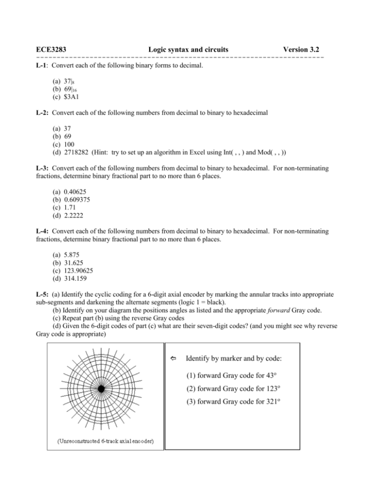
ECE3283 Logic syntax and circuits Version 3.2 ---------------------------------------------------------------------L-1: Convert each of the following binary forms to decimal. (a) 37|8 (b) 69|16 (c) $3A1 L-2: Convert each of the following numbers from decimal to binary to hexadecimal (a) (b) (c) (d) 37 69 100 2718282 (Hint: try to set up an algorithm in Excel using Int( , , ) and Mod( , , )) L-3: Convert each of the following numbers from decimal to binary to hexadecimal. For non-terminating fractions, determine binary fractional part to no more than 6 places. (a) (b) (c) (d) 0.40625 0.609375 1.71 2.2222 L-4: Convert each of the following numbers from decimal to binary to hexadecimal. For non-terminating fractions, determine binary fractional part to no more than 6 places. (a) 5.875 (b) 31.625 (c) 123.90625 (d) 314.159 L-5: (a) Identify the cyclic coding for a 6-digit axial encoder by marking the annular tracks into appropriate sub-segments and darkening the alternate segments (logic 1 = black). (b) Identify on your diagram the positions angles as listed and the appropriate forward Gray code. (c) Repeat part (b) using the reverse Gray codes (d) Given the 6-digit codes of part (c) what are their seven-digit codes? (and you might see why reverse Gray code is appropriate) Identify by marker and by code: (1) forward Gray code for 43o (2) forward Gray code for 123o (3) forward Gray code for 321o L-6: How many tracks does an axial encoder need to define angular position to within: (a) (b) (c) (d) position to within 10 sec of latitude on the Earth's surface? (sexagesimal system) the angle subtended by the planet Mars at zenith (look up necessary distances/diameters on the web)? 1 mr (milliradian) 0.02mm of position accuracy for node driven by a wire spooled over a 4 inch dia rotor? L-7: What is the largest size axial encoder (number of tracks) that can be read with the following systems? (a) System read rate = 50 kbit/sec, positioning wheel with maximum angular velocity 1200 RPM. (b) System read rate = 10 kbit/sec, mobile robot with tire dia. 30 cm and maximum forward speed 20 mi/hr. L-8: It is the year 2027 and the planet is at risk from intelligent 0.1km dia meteoroids who are on a suicide mission toward earth at 15 km/s. A ring of 8 defense satellites, each armed with 18-MW UV lasers capable of vaporizing incoming meteoroids of this size, provided that they can be held on target for 10 min or longer. They have to be locked on target by (non-intelligent) software and positioning systems. Assume that the satellites are in geosynchronous orbit (look up orbital specifications on the web). If an incoming meteoroid pops out from behind the moon (look up orbital specs on your website), (a) what size axial encoder (number of tracks) is needed for the satellite guarding that sector to lock its laser on the incoming meteoroid? and (b) what read rate (baud) of the encoder is necessary to compensate for the orbital velocity of the satellite (worst case)? L-9: Construct the truth table for each of the following logic functions (a) F AB AB (b) F AB AB (this is called a comparison gate) (this is called an exclusive-or (XOR) gate) (c) F ( AB BC ) (d) F ABC ABC ABC ABC (e) F ABC BC AB (f) F ABC A( B C ) L-10: Realize the following circuits in terms of AND and OR gates with any complement inputs denoted by input bubbles and any complemented outputs denoted by output bubbles. (a) (b) (c) (d) F AB AB F A B ABC F AB BC F ABC AC (this is also called an XNOR = exclusive NOR gate) L-11: Use DeMorgan's laws to find (1) the inverse of each of the following boolean expressions and (2) synthesize (the inverse) in AND-OR logic. To keep the circuit simple, you can use inputs in complement form, since the complement inputs are usually available anyway. (a) F ABC ABC ABC (b) F ABC A( B C ) (c) F A( B C ) BD (d) F AB ( A C ) D L-12: Find a way to (a) implement the two-input XOR function F AB AB using an AND-OR realization. Assume that both true and complement inputs are available. (b) implement the two-input XOR function F AB AB using only NAND gates. Assume that both true and complement inputs are available. (c) implement the two-input XNOR (comparison) function F AB AB using an AND-OR realization. Assume that both true and complement inputs are available. (d) implement the two-input XNOR (comparison) function F AB AB using only NAND gates. Assume that both true and complement inputs are available. L-13: Use DeMorgan's laws to (1) execute the inverse of the inverse of each of the following boolean expressions and (2) synthesize the function in terms of NAND gates only. Note that in order to do so you must first express the logic expression in a sum-of-products (SP) form, if it is not already. (a) F ABC ABC ABC (b) F ABC BC BC (c) F ABC A( B C ) L-14: Construct the 1's K-map for each of the following functions and minimize it into a result that has the fewest possible number of terms. Assume that both true and complement inputs are available for each variable. (a) F AC D ABC D BC D ABC BC D (b) F = m(0,1,2,4,5,8,10) (c) F = m(1,3,4,6,11,12,14) L-15: Construct the 0's K-map for each of the following boolean expressions and minimize the function into a result that has the fewest possible number of terms. Note: These expressions are (essentially) the same as those for problem L-14. The only difference is that you are making use of the complement map. (a) F AC D ABC D BC D ABC BC D (b) F = m(0,2,3,6,7,8,10) (c) F = m(1,3,9,11,12,14) L-16: For each of the following functions minimize and simplify using the 1's K-map and synthesize these circuits using an AND-OR realization. Assume that both true and complement inputs are available for each variable. (a) F ABC D AB D ABC AC D (b) F abd abc acd bcd abc bcd (c) F = m(2,3,5,6,7,9,11,13,15) (d) F = m(1,3,9,11,12,14) L-17: For each of the following functions minimize and simplify using the 1's K-map and synthesize these circuits using nothing but NAND gates. Simplification: Complement inputs are normal (and desirable) for your finished circuit (there is no need to clutter up the circuit with inverters at the inputs). (a) (b) (c) (d) F ABC D AB D ABC AC D F abd abc acd bcd abc bcd F = m(0,1,4,8,10,12,14) F = m(1,3,9,11,12,14) L-18: Use K-maps to determine the functions (x,y,z) needed to realize a code converter that converts from reverse-Gray to arithmetic binary (see accompanying truth tables) for: (a) x (b) y (c) z Do not realize the circuit. Just find the functions L-19: Use K-maps to determine the functions (A, B, C) needed to realize a code converter that converts from reverse-Gray to arithmetic binary (see accompanying truth tables) for: (a) A (b) B (c) C Do not realize the circuit. Just find the functions L-20: The following represents the simplest alpha-numeric display element that can be created using 4ft fluorescent light bulbs. Make full use of the don't-care outputs (for the unused inputs) to minimize segment drivers. (a) (b) (c) (d) (e) (f) Synthesize segment a using a minimized NAND-only format. Complement inputs are acceptable. Synthesize segment b using a minimized NAND-only format. Complement inputs are acceptable. Synthesize segment c using a minimized NAND-only format. Complement inputs are acceptable. Synthesize segment d using a minimized NAND-only format. Complement inputs are acceptable. Synthesize segment e using a minimized NAND-only format. Complement inputs are acceptable. Synthesize segment f using a minimized NAND-only format. Complement inputs are acceptable. (g) Synthesize segment g using a minimized NAND-only format. Complement inputs are acceptable. L-21. The fail-safe sensors for the backpack fuel cell consists of two pressure sensors (P, p) and two thermal sensors (T,t) deep within the system. It is desired that the ‘system unsafe’ alarm go off if pressure > 10 psi anywhere in the system or if temperature < 95o, anywhere in the system. The truth table can be identified as shown. Design the simplest NAND-NAND realization necessary to accomplish this requirement using the four sensors as inputs (Hint: take advantage of the "don't care" inputs). L-22. The following circuit represents a sample/and hold serial-parallel shift register using DFFs with input pulse code string as indicated Identify the outputs for Q0, Q1, Q2, Q3, Q4 and Q5 and identify their values 7 clock cycles after the clock enable (sample input) goes high. L-23: (a) For the shift register shown, determine the state table and state diagram (Mealy) of the circuit (= finite state machine). (b) Assuming that the initial state is (Q0 Q1) = (0 0) find the successive states for x = 1 (i.e. x = 1111111...) and corresponding value (string) for z. L-24: Assuming that the initial state of the shift register shown is (Q0Q1Q2) = (1,0,0) find the successive states for the cases of x = 0 and x =1, respectively. For x = 1 after how many cycles will the register return to its starting state? L-25: Determine the state table and state diagram (Mealy form) for the finite state machine (FSM) represented by the circuit of problem L-24. Take note that you will have eight states. L-26: Repeat problem L-25 with the 2-input XNOR gate replaced by a NOR gate (as shown) and determine the output (z) string if the input string is 010101 and the starting state is (Q0Q1Q2) = (1,0,0).


