transport
advertisement

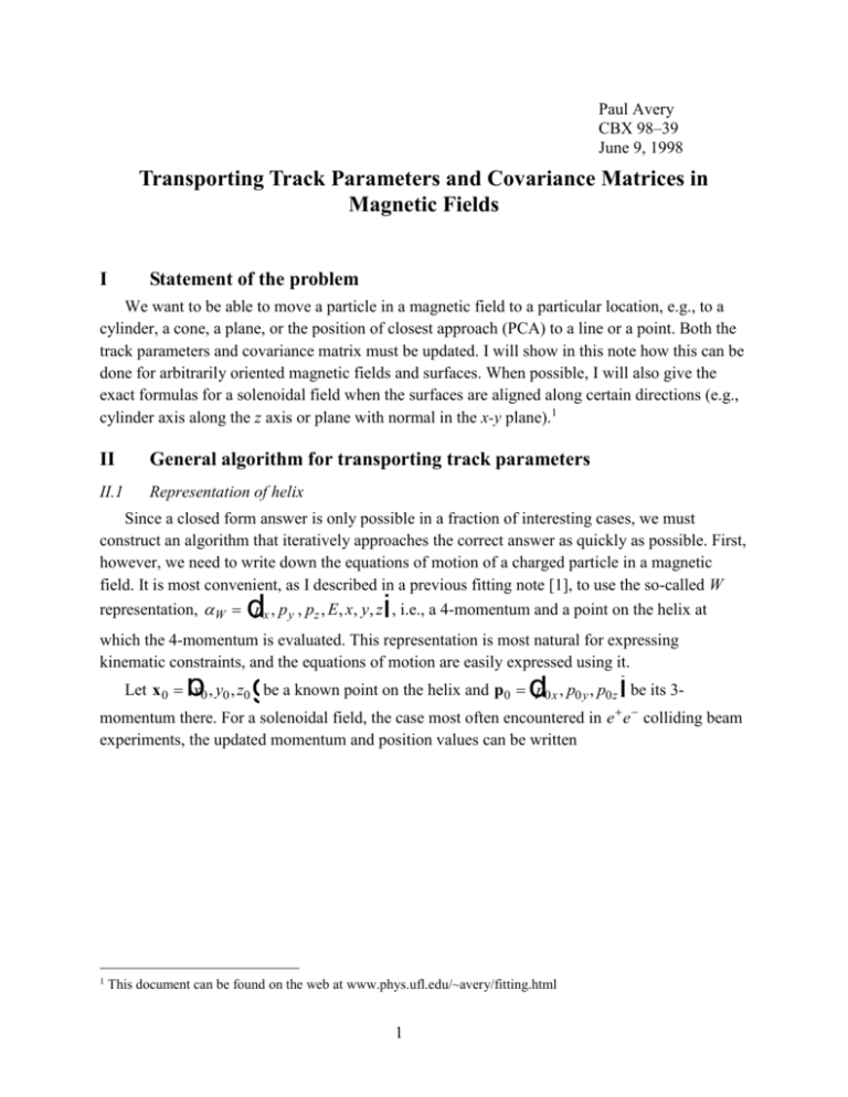
Paul Avery CBX 98–39 June 9, 1998 Transporting Track Parameters and Covariance Matrices in Magnetic Fields I Statement of the problem We want to be able to move a particle in a magnetic field to a particular location, e.g., to a cylinder, a cone, a plane, or the position of closest approach (PCA) to a line or a point. Both the track parameters and covariance matrix must be updated. I will show in this note how this can be done for arbitrarily oriented magnetic fields and surfaces. When possible, I will also give the exact formulas for a solenoidal field when the surfaces are aligned along certain directions (e.g., cylinder axis along the z axis or plane with normal in the x-y plane).1 II General algorithm for transporting track parameters II.1 Representation of helix Since a closed form answer is only possible in a fraction of interesting cases, we must construct an algorithm that iteratively approaches the correct answer as quickly as possible. First, however, we need to write down the equations of motion of a charged particle in a magnetic field. It is most convenient, as I described in a previous fitting note [1], to use the so-called W representation, W px , p y , pz , E, x, y, z , i.e., a 4-momentum and a point on the helix at d i which the 4-momentum is evaluated. This representation is most natural for expressing kinematic constraints, and the equations of motion are easily expressed using it. b g d i Let x 0 x0 , y0 , z0 be a known point on the helix and p0 p0 x , p0 y , p0 z be its 3momentum there. For a solenoidal field, the case most often encountered in e e colliding beam experiments, the updated momentum and position values can be written 1 This document can be found on the web at www.phys.ufl.edu/~avery/fitting.html 1 px p0 x cos s p0 y sin s p y p0 y cos s p0 x sin s pz p0 z p0 y p0 x sin s 1 cos s a a p0 y p y y0 sin s 0 x 1 cos s a a p z z0 z s p b b x x0 g g (1) where a 0.299792458Bq , B is the magnetic field strength in Tesla, q is the charge and a / p . These equations are functions of s, the arc length measured from the initial point x 0 to x x, y, z . a f The exact equations describing the new helix parameters in an arbitrarily oriented, constant magnetic field can easily be generalized to [1] d i d i h sin s d p h ih a 1 cos sf p p 0 h h cos s p 0 h sin s p 0 h h p 0 cos s p 0 0 E E0 (2) p h i h d p sin s h p h 1 cos s 0 h s a a p p p h p h sin s x 0 0 sin s 0 1 cos s 0 h s a a p x x0 0 0 a a f F G H f IJ K where h is a unit vector in the direction of the magnetic field. Over a sufficiently small region the equations can be accurately represented to second order in s x x0 p0 p h 2 s 0 s p 2p d 2 2 p p0 1 12 s II.2 (3) i dp h is h dp h i 0 0 1 2 2 2 s Definition and use of the indicial equation in this paper The strategy for computing the desired location on the helix, which can be either an intersection point with a surface or a point of closest approach, is simple. The track has 3momentum p0 p0 x , p0 y , p0 z at the position x 0 x0 , y0 , z0 . We substitute eqns. (2) for x d b i g and p into the equations which describe the place we want to move to (these are at most second order in the position coordinate) and then truncate the resulting expressions to second order in the arc length s, yielding the so-called indicial equation 2 as 2 bs c 0 (4) Solving this equation for s gives two solutions, so we choose the smallest positive value of s, representing the solution closest to the current point in the direction of motion. Once we have the approximate value of s, we use the exact transport equations in eqn. (2) to move the parameters closer to the correct point. This process is repeated until the distance moved falls below a cutoff value. This quadratic interpolation procedure converges extremely rapidly. III Specific cases for transporting track parameters For each specific case in this section, I provide the equation that describes the place to which we want to move the track. Substituting eqns. (3) into this equation yields the indicial equation as 2 bs c 0 which can be solved for s. Once s is obtained the track parameters are updated using the exact formulae in eqn. (2) and the process repeated until s becomes small enough. Note that when the track is a straight line ( 0 ), the indicial equation is exact. This is because the track becomes a linear function of s and the equations defining the surfaces or point of closest approach are at most second order in the coordinates. III.1 Intersection with a plane d i The equation of a plane is x x p 0 , where x p is a point on the plane and is a unit vector in the direction of the normal to the plane. The general indicial equation is F p I F p h I sG G J Hp K H p J Ks 0 0 1 2 2 0 (5) where x 0 x p . It is also worthwhile to work out two cases that can be solved for s exactly. When h is perpendicular to (e.g., barrel silicon plane in a solenoidal magnetic field), the exact indicial equation is d i h p0 p0 h sin s 1 cos s 0 a a a f (6) which can be solved exactly for s: R U | a |V R |Sp a p p R U |V 1 cos s S |Tp a p p R |W|T p p |W dh i R | p R U |V R |Sp p a p p sin s a S |Tp a p p R |W|T p p 2 2 2 2 2 2 2 3 2 2 R (7) U |V |W where R p2 2 a p a 2 2 , , p p 0 and p p 0 h . The first term on the RHS should be used when the closest intersection point is to be found or if a is close to zero. The other case is when h is parallel to (e.g., plane at a fixed z position in a solenoidal magnetic field. The exact indicial equation is dh || i p0 s0 p (8) which can be solved for s trivially. III.2 Intersection with a cylinder 2 d i The equation of a cylinder surface is x x p R2 , where x p is the center of the cylinder (actually any point on the axis), R is the radius and is a unit vector pointing in the direction of the cylinder axis. The indicial equation is p p I F p F 1 G H p J Ks G Hp 2 2 R2 2 2 2 I J K p0 h p 0 h 2 s 0 p p (9) where x 0 x p , and p p 0 . d i When the cylinder axis is aligned along the magnetic field h 1 , e.g., when the cylinder axis is along z in a solenoidal field, it is possible to solve for s exactly. The exact indicial equation is p p I F G H p J Ksin s p h I 2 F p 1 1 cos s 0 G J p H p Ka f dh 1i 2 2 R2 2 0 2 2 (10) 0 2 This has the solution R |S |T 2 2 2 2 2 2 A2 R A1 A2 4 A2 4 R A1 R 1 cos s 2 A12 2 A22 U |V |W dh 1i (11) R |S |T R , A 1 d p / p i d p h ia / pf and A d p U |V |W p i / p . 2 2 2 2 2 A1 A2 R A2 A1 4 A2 4 R A1 R sin s 2 A12 2 A22 where R 2 2 2 1 2 2 0 4 2 0 III.3 Intersection with a cone 2 d i 2 d i The equation of a cone surface is x x p x x p tan 2 , where x p is the apex of the cone, is the half-opening angle and is a unit vector pointing in the direction of the cone d i dx x i axis. This equation can be rewritten in simpler form: x x p 2 p 2 sec 2 . The indicial equation is d F1 p G Hp i 2 2 sec 2 p0 p sec 2 s 2 2 2 sec I J K p0 h p0 h sec 2 s 2 0 p p (12) where x 0 x p , and p p 0 . There is no case that can be solved exactly, unless the helix is a straight line. III.4 Point of closest approach to a reference point The equation describing the location of a point on the track can be found by requiring that a line starting at the reference point strike the helix at right angles to the direction of motion. This gives the equation p x x p 0 , where x p represents the coordinates of the reference point. d i The indicial equation is 2 2 p0 p p0 h s p0 h ph s 0 2 where x 0 x p , h h and ph p0 h . i b d g (13) Unfortunately, the indicial equation for this case does not specify whether the track is at the minimum or maximum point of closest approach. To go further we have to write the distance from the helix to the point as a function of the arc length s. Let d 2 be the distance squared from the reference point to a point on the helix. Then d 2 / s 0 should reproduce the indicial equation (to within a constant factor). To force the distance to be a minimum, we must in addition require 2d 2 / s2 0 . The best way to evaluate this is to move to the point of minimum/maximum distance. At that point, s = 0 and the second derivative is proportional to the coefficient multiplying the linear term in s in the indicial equation (13). Thus in addition to solving the indicial equation, we must also require p p 0 h 0 at the point to ensure that the point is at the distance of closest approach.2 When the helix is a straight line, the distance of closest approach to the point is a f b g/ p dPCA 0 2 p0 2 2 2 (14) Actually, the absolute sign of the linear term is not specified by this argument so one does not know a priori if we get a minimum or a maximum distance. However, I worked out the case by hand to determine that the condition shown here gives a minimum distance. 5 III.5 Point of closest approach in the bend plane to a reference point The equation describing the location of a point on the track can be found by requiring that a line starting at the reference point strike the helix at right angles to the direction of motion in the bend plane. This gives the equation p h x x p h 0 , where x p represents the d id i coordinates of the reference point. The indicial equation is 2 2 p0 h ph p ph2 / p p0 h s p0 h ph s 0 2 where x 0 x p , h h and ph p0 h . i b d g (15) Actually it is possible to find the exact solution for this case. Substituting the exact equations of motion in eqn. (2) into the equation describing the PCA location, we get b g d i p0 h ph cos s p ph2 / p p0 h sin s 0 (16) This has the solution A1 cos s A12 2 A22 (17) A2 sin s A12 2 A22 where A1 and A2 have the same meaning as defined previously for the cylinder case in eqn. (11), i.e., A1 1 ph2 / p 2 p0 h / p and A2 p0 h ph / p . The distance of closest d ia f id b g approach can then be calculated to be d PCA L M N L M M N 2 2 2 h 2 h 2 2 eA 1 2 A22 A12 2 A22 A1 jO P Q 1/ 2 A12 2 A22 O P P Q (18) 1/ 2 This can be simplified after a fair amount of algebra to dPCA p h a L p M 1 2a p M N 0 h 2 h a2 1 2 p0 h a 2 2h p h d 1 1 2a O P P Q 2 2h 1 p2 h i 2 2 p0 h 2 h a p2 h p2 h 6 (19) where p h p0 h . This modified formulation of dPCA has the advantage over the previous one of being a signed quantity, which is useful when doing lifetime studies. The versions with the square root in the denominator should be used when a is small. When the helix is a straight line (a = 0), eqn. (19) reduces to a f d PCA a 0 III.6 p 0 h p h (20) Point of closest approach to a straight line This case is important for transporting a track to the point closest to a drift chamber wire. Let the wire coordinates be described by x w x w 0 t , where is a unit vector along the wire and t is the distance from a nominal starting point x w 0 . We want to find the location on the helix where a line connecting it to a point on the wire is perpendicular to the wire and the direction of motion of the track. The two perpendicularity conditions allow us to solve for t and s. After some algebra, the indicial equation is found to be d p 0 p s p p2 / p p 0 h p 0 h s 2 i d i 3 p / p p 0 h p 0 p h ph ph h 0 (21) 2 where x 0 x w 0 , , p p 0 and h h . As in the problem of finding the point of closest approach to a point (Section III.4), the indicial equation does not indicate whether the helix is at the minimum or maximum distance to the line. As discussed in that section, the correct procedure is to move to the point satisfying the indicial equation criterion in eqn. (21) and require that the linear coefficient in eqn. (21) be positive there, i.e. p p2 / p p 0 h p 0 h 0 . When the helix is a straight line, the distance of closest approach can be found exactly as a f d PCA a 0 b g p0 p0 (22) where I have allowed it to be signed. When the wire lies along the magnetic field direction (axial drift chamber wire, for example), the problem is identical to finding the point of closest approach in the bend plane to a point, discussed in Section III.5 (compare to eqn. (20)). III.7 Intersection with a doughnut Since we have not specified glazed, cinnamon or custard-filled, it is impossible to proceed further. 7 IV Transporting the covariance matrix We now consider the question of how transport the 7 7 covariance matrix, corresponding to the seven quantities px , py , pz , E, x, y, z . If the new parameters are related to the original ones d i 0 by the linear equation A 0 , where A is a 7 7 matrix, then the covariance matrix can easily be found by propagation of errors to be V AV 0 A T (23) Of course, the equations that describe the relation of the new parameters to the old ones in eqn. (2) are not linear, but they can easily be made so by expanding about and 0 to first order. The matrix A is the partial derivatives of the new parameters with respect to the old ones, using eqn. (2). However, we must also include variations in the arc length s, which are different for each of the cases considered in the previous section. We compute the new covariance matrix, including the arc length variations, using a clever (if I say so myself) 2-step procedure. First, we apply the results of the previous section to find the arc length s between the old and new positions on the helix. The parameters are updated using eqn. (2). The matrix A is found by taking partial derivatives in eqn. (2), e.g., Aij i / 0 j , and then used to find the first approximation to the new covariance matrix via eqn. (23), assuming s is fixed. Next, we expand the helix to first order in s about the updated position: p p E E x x (24) p s p Since s 0 , the variations can be written p p E E x x (25) p s p where s can be found from the indicial equation, i.e. bs c 0 , and thus expressed in terms of variations of the original parameters, which were derived in Section III for each of the separate cases. The variations can be written A , thus the new covariance matrix is, in analogy to eqn. (23), V AV A T . References 1. Paul Avery, “Applied Fitting Theory VI: Formulas for Kinematic Fitting”, CBX 97–37, http://www.phys.ufl.edu/~avery/fitting.html. 8


