Continuously Variable Transmission and Regenerative Braking
advertisement
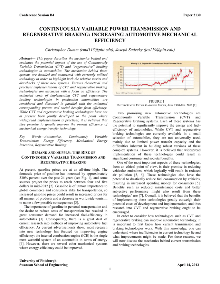
Conference Session B4 Paper 2130 CONTINUOUSLY VARIABLE POWER TRANSMISSION AND REGENERATIVE BRAKING: INCREASING AUTOMOTIVE MECHANICAL EFFICIENCY Christopher Dumm (cmd113@pitt.edu), Joseph Sadecky (jcs119@pitt.edu) Abstract— This paper describes the mechanics behind and evaluates the potential impact of the use of Continuously Variable Transmission (CVT) and “regenerative” braking technologies in automobiles. The mechanics behind these systems are detailed and contrasted with currently utilized technology in order to highlight both the relative merits and drawbacks of these new systems. Various theoretical and practical implementations of CVT and regenerative braking technologies are discussed with a focus on efficiency. The estimated costs of implementing CVT and regenerative braking technologies in production automobiles are considered and discussed in parallel with the estimated corresponding private and social benefits from efficiency. While CVT and regenerative braking technologies have not at present been jointly developed to the point where widespread implementation is practical, it is believed that they promise to greatly improve the overall efficiency of mechanical energy transfer technology. FIGURE 1 UNITED STATES RETAIL GASOLINE PRICES, AUG. 1990-FEB. 2012 [1] Two promising new automotive technologies are Continuously Variable Transmission (CVT) and Regenerative Braking systems. Each of these systems has the potential to significantly improve the energy and fuelefficiency of automobiles. While CVT and regenerative braking technologies are currently available in a small selection of automobiles, they are not universally used, mainly due to limited power transfer capacity and the difficulties inherent in building robust versions of these complex systems. However, it is believed that widespread implementation of these technologies could result in significant consumer and societal benefits. One of the most important aspects of these technologies, from an ethical point of view, is their promise in reducing vehicular emissions, which logically will result in reduced air pollution [5, 6]. These technologies also have the potential to drastically reduce fuel consumption by vehicles, resulting in increased spending money for consumers [5]. Benefits such as reduced maintenance costs and better subjective performance might also result from these technologies’ use [7]. Overall, it is believed that the benefits of implementing these technologies greatly outweigh their potential costs of development and implementation, and thus research into CVT and regenerative braking ought to be encouraged. In order to consider how technologies such as CVT and regenerative braking can improve automotive technology, it is important to first know how current transmission and braking technologies work. With this knowledge, one can understand where inefficiencies in current technology lie and what improvements might be made. For these reasons, we will now discuss the mechanics behind current transmission and braking technologies. Key Words—Automotive, Continuously Variable Transmission, Energy Efficiency, Mechanical Energy Retention, Regenerative Braking DEMAND AND SUPPLY: THE RISE OF CONTINUOUSLY VARIABLE TRANSMISSION AND REGENERATIVE BRAKING At present, gasoline prices are at an all-time high. The domestic price of gasoline has increased by approximately 330% percent over the past 24 years (see Fig. 1), and some sources project the prices to reach between four and five dollars in mid-2012 [2]. Gasoline is of utmost importance to global commerce and consumers alike for transportation, so increased gasoline prices could result in increased prices for all manner of products and a decrease in worldwide tourism, to name a few possible consequences [3]. The importance of gasoline in personal transportation and the desire to reduce costs of transportation has resulted in great consumer demand for increased fuel-efficiency in automobiles [3]. Consequently, there is a great deal of current research into methods of improving automotive fuel efficiency. As current advertisements show, most research into new technology has focused on improving engine efficiency: the internal combustion engine (ICE) is the single most wasteful system of an automobile in terms of energy [4]. However, there are several other mechanical systems where energy-efficiency could be improved. University of Pittsburgh Swanson School of Engineering April 14, 2012 1 Christopher Dumm Joseph Sadecky manual and automatic transmissions. Both typically have between four and six gears, but each uses a different method to switch between them. In automatic transmission vehicles, the automobile’s computer selects the appropriate gear reduction for the vehicle and initiates gear changes. Mechanically, this action is accomplished with a device called a torque converter, which couples two shafts through internal movement of a high-pressure fluid while switching gears (see Fig. 2). Manual transmission systems, however, switch between gears with an operator-controlled gear lever and a clutch (a physical coupler for the gear-reduced engine shaft and output shaft.) To shift, the operator depresses a pedal which disconnects the automobile’s clutch, and while disconnected the operator can switch gears [8, 9]. CURRENT APPROACHES: TRANSMISSION The power transmission systems of modern automobiles are not a drastic departure from previous technology; in fact, they are very similar to those of the first automobiles built over 100 years ago. The transmission system serves to connect the rotational output of a combustion engine to the automobile’s wheels. This system can be abstractly broken up into two subsystems. The larger of these two subsystems physically is the vehicle’s drivetrain, which includes the main drive shaft. This shaft is connected to the automobile’s wheels and causes them to turn. However, the drive shaft must be turned by the engine. This action is accomplished by the second subsystem: the gear reduction process [8]. When the automobile’s engine is running, the engine turns a shaft with energy produced through gasoline combustion. As the accelerator pedal is depressed, the rate of combustion is increased, and so the shaft rotates faster. Without a “load,” another mass for the shaft to turn, the output shaft of the engine spins at a very high speed, usually several thousand rotations per minute (RPM). This is similar conceptually to how a dentist’s drill spins at a very high speed when not in contact with a tooth. However, when contact is made, the drill spins much more slowly: when loaded, the energy that previously created high rotational speeds is expended on the load. Similarly, a significant load attached suddenly to an engine would slow the engine down. However, such an abrupt action would be violent, and could cause damage [8]. The gear reduction process creates a stable, “artificial” load by connecting the engine output to the wheels through a set of gears. These gears effectively reduce the angular velocity, or turning speed, of the shaft significantly. There are three major effects that make gear reduction valuable. To begin, the slower output of a “geared-down” engine can be produced with less power than with a direct engine-shaft connection. This lower speed is more easily handled by an operator and thus increases road safety. Finally, the reduced speed is more stable since the engine has more power available to respond to load changes: more turning force, or “torque,” is available with a geared-down engine [8]. However, the amount of torque the engine produces depends on the gear reduction. Different gear reductions produce different torques, which have applications in different situations. In a standard bicycle, several interchangeable gears are available. Some gears are meant to help produce small, accurate adjustments when moving at high speed, while others are meant to help provide power in situations like hill climbing. Overall, the purpose of gearing is to reduce the power requirements of the engine (or in this case, the human). This type of situational adaptability cannot be replicated by a single gear reduction: with multiple gears, more efficient power utilization is possible [8]. Just like bicycles, automobiles must have efficient mechanisms to control torque at the wheels. The transmission system fulfills this need. Currently, there are two main approaches to transmission design in vehicles: FIGURE 2 EXPLODED VIEW OF A TORQUE CONVERTER [9] Current transmission systems can be improved in the gear reduction process. Significant losses in energy occur during the switching action in both types of transmission: the fluid in a torque converter does not transfer power between shafts at a 1:1 ratio, and a manual transmission vehicle’s engine output is wasted when the clutch is disconnected. Additionally, since each gear reduction is most effective at a specific speed, energy is not as effectively utilized when the engine runs at different speeds [7, 8, 9]. CURRENT APPROACHES: BRAKING Moving vehicles have a great deal of translational kinetic energy (energy by virtue of displacement). In order to bring a vehicle to rest, this energy must be eliminated. With the engine disconnected, friction between a vehicle’s wheels and a road surface will eventually eliminate this energy, but efficient highway movement and quick action in emergencies necessitate a faster-acting method of slowing a vehicle. Braking systems fulfill this need [8, 10]. Braking systems remove energy with friction, the same mechanism which slows vehicles on a road. However, in a braking system, this friction is operator-controlled and of a 2 Christopher Dumm Joseph Sadecky greater, yet variable, magnitude. The operator controls motion with braking by reducing the rotational kinetic energy of the vehicle’s axles: this energy is converted by the wheels to translational kinetic energy, so a reduction in rotational kinetic energy results in a reduction of translational kinetic energy. One braking system variant (shown in Figure 3), “disc” brakes, use a hydraulic caliper to clamp several brake pads down onto a rotor, a hardened metal disc coaxial with the vehicle’s wheels. The rotational kinetic energy is converted to heat, and is said to be “burned off” in friction. This process is virtually the same one used for braking in bicycles, and while other braking system variants exist, they all have similar mechanics [8, 10]. However, a significant reduction in vehicular greenhouse gas emissions could still be accomplished by increasing automotive fuel economy. Increased fuel economy reduces the rate of gasoline combustion in an engine, and therefore results in reduction of vehicular emissions [1, 6]. Because of this correlation, it is clear that increased automotive energyefficiency results in a reduced rate of global warming. It could be argued on the basis of global warming that the design and implementation of more efficient transmission and braking technology than currently exists is ethically mandated. We have determined that current systems are inefficient in specific areas: transmissions have inefficient gear reduction, while braking utilizes inefficient mechanics outright. According to the Second Law of Thermodynamics, complete retention of the energy lost in these systems is impossible, but significant improvements can be and are currently being made in automotive technology [10]. We turn now to the description and analysis of two types of systems that have the potential to improve automotive energy-efficiency: Continuously Variable Transmissions and regenerative braking. In order to analyze these systems, we intend to first describe the theoretical mechanics of these systems, and then consider what real-world factors will reduce these systems’ performances. Ultimately, in order to be considered worthwhile additions, CVT and regenerative braking systems must save enough energy over the vehicle’s lifetime to cover manufacturing costs. Over the lifetime of a normal vehicle, a certain amount of energy is expended in materials, manufacturing, use, and disposal cycles (see Fig. 4). As the figure shows, approximately 83% of this total energy is contained in the “use” cycle, which is mainly obtained from gasoline combustion, while 15% of this energy is used in manufacture of the entire vehicle [12]. This energy usage can be considered characteristic of all consumer automobiles. In all cases, we can safely assume that the energy costs of implementing CVT and regenerative braking systems are less than one-third of the total manufacturing energy cost (5% of total energy). The equivalent of 5% of total energy is a 6% savings in the use cycle; thus, any automotive system that provides above a 6% increase in fuel-efficiency is without question worthwhile. We will gauge the effectiveness of current CVT and regenerative braking systems on this basis. FIGURE 3 A STANDARD AUTOMOTIVE DISC BRAKE SYSTEM [11] The energy efficiency of modern braking systems of modern automobiles could also be increased. The energy “burned off” by friction brakes exits the system into the atmosphere as heat. While these systems are necessary for coming to a complete stop and absolutely vital for emergency stopping, all of the kinetic energy in the system is entirely wasted during friction braking [10]. THE VALUE OF INNOVATION Current automotive transmission and braking systems are energy-inefficient in multiple ways. Using more energyefficient systems in automobiles will logically result in increased automotive fuel efficiency, which has obvious benefits in financial savings for consumers [3]. However, there is an environmental issue of greater importance than consumer savings impacted by automotive fuel efficiency. In chemical terms, combustion of gasoline produces carbon dioxide and other greenhouse gases [1, 6]. The role of greenhouse gases produced by vehicular emissions in global warming hardly needs to be stated: the media has brought this serious environmental threat to worldwide attention over the past decade [1, 6]. While the rate of atmospheric pollution would be decreased significantly if consumer automobile use were eliminated entirely, the complete elimination of private vehicle usage is absurd. FIGURE 4 AUTOMOTIVE ENERGY USE OVER PRODUCT LIFE CYCLE [12] 3 Christopher Dumm Joseph Sadecky EFFICIENT POWER UTILIZATION: CONTINUOUSLY VARIABLE TRANSMISSION CVT IN PRACTICE: CURRENT PERFORMANCE Because a CVT can provide the most efficient gear reduction for a given situation near-instantaneously, a CVT-equipped vehicle ought to (and has proven to) be more fuel-efficient than current vehicles [13]. The consumer benefits of CVT technology are obvious: increased fuel economy results in reduced fuel purchases, and therefore less variable cost of owning and operating an automobile. In societal terms, emission levels will be reduced as compared to vehicles with standard transmissions, since gasoline combustion is minimized [13, 14]. One qualitative benefit of this technology is smoother performance: in an automobile with a standard transmission style, a jerk is often felt when switching between gears, but since CVT gear reduction occurs without interchanging components, this jerk is virtually eliminated [14]. Real CVTs will exhibit these characteristics, but practical constraints will have an impact on CVTs’ real-world performances. Of note is the fact that real CVTs are not ‘infinitely’ variable: upon reconsidering Fig. 4, it is clear that the precision of the displacement mechanism and vibrations within the system’s belt will limit the range of possible CVT gear reductions [13]. However, this range is certainly greater than that of a standard transmission; thus, the CVT is superior in this regard. Of more concern is the belt connecting the pulleys. While automobile manufacturers produce their own belts, usually made of high-strength steel, all belts in CVT systems are under enormous stresses while in operation. These belts are continually subjected to great tension, and the force distribution across the belt is not uniform: since the belt contacts the rollers at its edges, forces keeping the belt in place act at the belt’s edges [13]. The materials used to create these belts will deform and break when too much force is applied; thus, there is a limit to the amount of power that can be transferred through a pulley-based CVT [13, 14]. At present, the limit of power that a CVT can handle is approximately 290 horsepower [15]. However, this power output is characteristic of the small vehicles in which CVTs are currently being implemented: current sedans have engine power in the range of 150-300 horsepower [16]. While 290 horsepower is within the sedan power range, it is on the lower side of current coupe power [17]. However, as CVTs can transfer power characteristic of sedans, CVT technology may be considered suitable for current applications. Quantitatively, CVT systems succeed in energy- and fuelefficiency. As stated previously, a system reducing use-cycle energy consumption by approximately 6% is sure to make up for its costs of implementation in energy savings. Current implementations of CVTs far exceed this 6% increase in efficiency: The Nissan XTRONIC CVT system increases fuel economy by 10%, according to in-house research [18], and the CVT system in a 2012 Subaru Impreza vehicle provides a similiar boost in fuel economy [19]. Like older systems, Continuously Variable Transmissions provide a gear reduction mechanism that connects an automobile’s engine with its drive shaft. However, the phrase ‘gear reduction’ seems somewhat improper when referring to CVTs: a continuously variable transmission does not, in fact, contain any gears at all. In their place, a CVT uses a form of ‘infinitely variable’ pulley and roller mechanism to create an effective gear reduction [13, 14]. The most basic CVT system (see Fig. 5) is composed of two sets of two conical rollers and a belt connecting them. By changing the distance between the rollers in a set (and thus the effective radius of the belt’s curvature), it is possible to create the equivalent of multiple gear reductions, like one would find in a standard transmission. However, the number of effective gears that can be created with this technology far exceeds the four to six gears found in standard transmissions. Additionally, because the positioning mechanisms of these rollers are computer-controlled, the effective gear reduction can be altered on-the-fly in response to the current speed of the vehicle and desired driver acceleration. These mechanics mean that the number of effective reductions that can be created is theoretically infinite. Additionally, switching between gears can be accomplished in small time: thus, the name “Continuously Variable” is apt. Perhaps the most important aspect of CVT technology, however, is the continued engine-drivetrain connection while switching gears. The consequences of this connection are thus: with theoretically infinite gear reduction capabilities and the continual engine-drivetrain connection, the energy lost while switching between gears in a standard transmission is retained. The efficiency of the system is also improved, as the CVT can provide the most efficient gear reduction possible for a vehicle at all times [7, 13, 14]. FIGURE 5 AN EXAMPLE OF THE OPERATION OF A PULLEY-BASED CVT SYSTEM [13] Many different implementations of CVT technology exist. Each manufacturer builds its own CVTs for use in its automobiles [14]. However, all versions are, in general, based on a computer-optimized and adjusted mechanism that effects a gear reduction between an engine and a drive shaft. 4 Christopher Dumm Joseph Sadecky This quantitative data supports earlier assertions regarding efficiency. The reduction in gasoline costs for consumers resulting from CVT use and the associated societal benefit of reduction in vehicular emissions clearly show that CVT implementation is ethically sound. Since CVT systems can handle the engine power of their target vehicle market and they provide significant societal benefits, we may conclude that implementing CVT systems in modern automobiles is in the best interest of all. on demand [10]. Therefore, a battery or capacitor would serve as an excellent energy storage medium. However, there is a problem present: how does one convert rotational kinetic energy to electrical energy? This problem has already been solved, and the solution is currently implemented in every production automobile. All automobiles contain a battery, which is used to start the engine, power the headlights and onboard computer, and so on. This battery discharges continually to power the vehicle’s systems: a way to recharge it in operation was needed. The solution was to use the engine itself to charge the battery. The device that accomplishes this is the alternator, which is composed of two main components: a set of magnets attached to a rotating shaft and a coil of wire that encloses the travel area of the magnets (see Fig. 4). When the magnets spin within the coil, a rotating magnetic field is created and an electric current is induced in the coil, which can then be used to power a circuit, or for the purpose of regenerative braking, to charge a battery or capacitor [21]. RETAINING ENERGY: REGENERATIVE BRAKING A regenerative braking system’s purpose is to remove translational kinetic energy from a vehicle, store that energy to be accessed later (as opposed to friction brakes, which remove the energy from the system outright), and to reconvert the stored energy to translational energy when required [20]. Therefore, a regenerative braking system has three essential components: a way to remove translational kinetic energy efficiently from a vehicle; some way to store that energy efficiently; and a way to convert the stored energy back into translational energy. We now consider some possible methods of regenerative braking. To begin, recovery of heat energy from the friction brakes is not an option: it is extremely difficult to recover and use heat energy [10]. Therefore, a regenerative braking system needs to act in place of the friction brakes in removing energy. The standard braking system removes rotational kinetic energy from the vehicle’s axles, so it seems most logical to remove energy from the axles in a similar way. As always, a complete, controlled stop requires friction brakes, but a regenerative braking system can retain some energy that is normally lost. In addition, since regenerative braking involves decreased use of the friction brakes, a vehicle’s brake pads will not need replacement as frequently, saving the consumer money. The two most promising methods of regenerative braking currently under research (and limited implementation) are regenerative braking based on kinetic energy storage and electrical energy storage. Each of these systems has its own strengths and weaknesses, but overall, each provides a feasible way to implement regenerative braking, which means that when used efficiently, the range and therefore fuel economy of the automobile will be extended. FIGURE 4 EXPLODED VIEW OF A STANDARD AUTOMOTIVE ALTERNATOR [21] This phenomenon is explained by Faraday’s Law of Induction. When applied to this situation, this law states that a magnetic field can induce a current in a wire, and vice versa [10]. This principle is the same one that explains how an electric motor works: the motor operates by passing a current through a coil of wire, which then creates a rotating magnetic field and induces rotational motion in a series of magnets attached to an axis [10]. In fact, the motor and the alternator are the same physical device: the specific motor/alternator behaviors are created by either passing a current through the coil or moving a magnetic field inside the coil [10]. The dual uses of this device are the key to electrical regenerative braking technology. Electric vehicles such as the Chevrolet Volt use a motor and a supply of batteries in place of the conventional ICE and gasoline combination [22]. When running, the motor is powered by current from the batteries. This supply can be switched on and off at will, but the connection to the vehicle’s drive shaft remains; consequently, if the drive shaft turns while the current to the motor is off, current will be induced in the motor. This induced current can be used to charge a capacitor or battery, which can be used as an Faraday’s Law of Induction and Electric Regenerative Braking We have established that the best way to remove kinetic energy is by removing rotational kinetic energy from the vehicle’s axes in a similar way to friction brakes, but we still need the actual components that will perform the regenerative braking task. Let us consider the storage medium. The first energy storage devices one tends to think of are energy storage units are batteries and capacitors: they can store a large amount of electrical energy and release it 5 Christopher Dumm Joseph Sadecky electrical energy source for the vehicle [22]. The production of current allows regenerative braking action. For an example of how this system might be useful practically, imagine a conventional vehicle coasting down a hill. The vehicle would naturally pick up speed as it goes further down the hill, necessitating the use of brakes to maintain a constant speed. But in this configuration, kinetic energy is converted to electric current in the motor (which acts as an alternator). This current can be used to recharge the batteries of the car, which results in an increase in stored energy that can be used to drive the vehicle further without recharging the vehicle. The relevance of this law is that the wheels of an automobile are themselves nothing more than flywheels that contact the ground. If the wheels were connected (through the drive axle) to a flywheel, this flywheel could slow the vehicle by charging and could move the vehicle from rest, which is a regenerative braking action. REGENERATIVE BRAKING IN PRACTICE: ITS IMPLEMENTATION AND IMPACT The fuel savings that regenerative braking systems promise to provide stand on their own merits: it is clear that regenerative braking would increase automotive energy- and fuel-efficiency and therefore decrease vehicular emissions, in addition to reducing maintenance costs. However, we must evaluate whether these systems are truly practical and valuable in the real world. What factors might reduce regenerative braking systems’ efficiencies? Inertia and Kinetic Regenerative Braking The regenerative braking systems described would certainly be useful for smaller vehicles capable of running on an electric motor, but larger vehicles such as vans or trucks require power that current electric motors are incapable of providing, and so would use an ICE. However, an ICE does not have the motor-alternator relationship to harness for regenerative braking, and the battery network required for alternator-based regenerative braking adds significant weight, costs and complexity, as evidenced by the $40,000+ price of the Chevrolet Volt [22]. Therefore, a different method must be used to implement regenerative braking in these vehicles. Capacitors and batteries are electrical energy storage units appropriate for regenerative braking systems, but their use requires conversion of rotational kinetic energy to electrical energy. This conversion is not strictly necessary: only a need to remove and store energy from the drive axles exists. One device capable of storing significant mechanical energy is a flywheel, which is essentially a massive disc. A flywheel is installed on an axis, and according to (1), when spun, or “charged”, has rotational kinetic energy proportional to its mass and angular velocity [10]. As a flywheel can act as an energy storage unit, the remaining question is of how to transfer energy between the main axles of a vehicle and a flywheel. 𝐸𝑘 = 1 2 1 𝐼𝜔2 ; 𝐼𝑓𝑙𝑦𝑤ℎ𝑒𝑒𝑙 = 𝑚𝑟 2 2 Electric Regenerative Braking in Practice In an electrical regenerative braking system, there is really only one component to discuss: the alternator/motor’s efficiency. As we know from the Second Law of Thermodynamics, the alternator can never retain all rotational energy in the system, but does it make the 5% benchmark necessary to justify its cost? To begin, it should be noted that the costs of implementing regenerative braking in electric cars will naturally be minimized. Because the motor can be used as an alternator, implementing a regenerative braking system would simply involve controlling a charging connection to the vehicle’s battery packs by computer. The merits of electrical regenerative braking are clear when considering electric hybrid vehicles such as the Chevrolet Volt. In EPA testing, the Volt had an alternator efficiency of over 90%, which, over the vehicle’s life cycle, will result in far greater energy savings than the costs of installing the regenerative systems [22]. A 2010 study on the impact of regenerative braking on vehicular emissions concurs with this savings: test bed vehicles and simulations suggested that regenerative braking could increase energy efficiency by at least 30%, which is clearly above our 6% guideline [6]. This real-world data supports our analysis. Electric regenerative braking systems are extremely effective at improving automotive efficiency; thus, these systems have the potential to significantly reduce vehicular emissions. (1) According to the Law of Conservation of Angular Momentum, the total angular momentum in a closed system is constant [10]. The consequence of this law is best explained by example. Imagine a flywheel being spun at a fast speed. If another identical but stationary flywheel were connected to the shaft of the first flywheel, the spinning flywheel would decelerate and the stationary flywheel would accelerate: they would come to an equivalent speed less than that of the original flywheel. The rotational kinetic energy of the first flywheel would be distributed between both flywheels when connected. Kinetic Regenerative Braking in Practice The kinetic-based regenerative braking system can be evaluated in the same way as the electrical braking system. The main component that needs to be discussed, in this case, 6 Christopher Dumm Joseph Sadecky is the efficiency of the flywheel as an energy storage mechanism. One disadvantage of kinetic-based regenerative braking is that the stored power is not universally distributable within the automobile. In an electric system, stored power can be used to power any of the vehicle’s components, but the kinetic energy stored by a flywheel can only be used to turn the vehicle’s axles unless an alternator is installed to convert the flywheel’s rotational energy to electrical energy. However, this disadvantage is offset by a significant increase in energy storage capabilities. Electrical systems’ energy storage capabilities are limited by the maximum storage potential of batteries or capacitors [10], whereas flywheel-based systems are only limited by the maximum speed of the flywheel before centripetal force tears the flywheel apart [10, 22, 23]. One other limiting factor in energy storage is friction between the flywheel shaft, bearings, and drivetrain, as well as air resistance. Just like an ordinary braking system, these sources of friction will reduce the flywheel’s rotational kinetic energy over time. Friction between the bearings, shaft, and drivetrain can never be fully eliminated when a physical connection between them exists, but the impact of air resistance can be minimized [10, 20]. One method of minimizing this impact is the placement of the flywheel in a sealed chamber under vacuum [20, 23]. However, creating such a system requires a significant investment in materials and manufacture [20]. The method of reducing air resistance used in Formula racing’s KERS (Kinetic Energy Recovery System, pictured in Fig. 5) is a partial vacuum: the flywheel is located within a chamber that can be placed under partial vacuum by a built-in vacuum pump [20, 23]. This method results in reduced air friction, reduced costs as compared to a sealed vacuum chamber, and ultimately increased energy retention within the vehicle [20, 23]. Formula racing’s KERS systems have experimentally shown a recovery of 70% of braking energy [20]. Theoretically, when scaled to the size of a standard vehicle, this energy savings could recoup the system’s cost over a year of driving [20]. While there are currently no production automobiles with flywheel-based regenerative braking systems, based on the KERS systems’ efficiency, it seems highly probable that such a system’s energy savings would justify the system’s cost. When considering the environmental benefit of reduced emissions due to reduced fuel consumption, this justification becomes even stronger. right, so it seems that a combination of these technologies in the same vehicle would be even more efficient. FIGURE 5 A FORMULA 1 RACING KERS SYSTEM [23] Currently, there are no production systems that concurrently implement true CVT and regenerative braking technologies. This may seem surprising given the increased efficiency of these technologies. However, it is important to remember that while the theory behind these systems may be relatively simple, building robust physical systems from basic materials for production use requires significant testing and design cycles to ensure quality and safety. Nevertheless, information is available on one system that currently implements regenerative braking and a system similar to CVT technology: the Toyota Hybrid Synergy Drive used in their Prius vehicle. This system’s fuelefficiency is due in a large part to their regenerative braking systems and their planetary gear drive [24], which has similar characteristics to the CVTs discussed. The 50 miles per gallon fuel-efficiency statistic of this vehicle attests to the efficient performance of this system, and to the likely performance of a vehicle with true CVT and regenerative braking technologies implemented concurrently [5]. CONSUMERS, SOCIETY AND THE ENVIRONMENT: JUSTIFICATION FOR CONTINUED DEVELOPMENT Based on our evaluation, it is clear that Continuously Variable Transmission and regenerative braking technologies could significantly affect the world when fully implemented. Both CVT and regenerative braking offer significant increases in automobile fuel economy when installed in vehicles. This increase in fuel economy results in a decrease in overall vehicular emission of greenhouse gases from gasoline combustion: by increasing the range an automobile can travel with a constant supply of fuel, these technologies will directly assist in reducing current growth of global warming. However, these technologies have additional benefits. While CVT and regenerative braking lead to reduced emissions and minimized air pollution, they also provide significant private benefits that would interest consumers. A consumer would desire an automobile with both of these CVT WITH REGENERATIVE BRAKING: MAJOR INCREASE IN MECHANICAL EFFICIENCY The CVT and regenerative braking systems that have been described are unquestionably valuable additions to modern automobiles. These systems individually provide significant consumer savings in fuel costs and maintenance costs as well as a major environmental benefit in reduced emissions. CVT and regenerative braking are each efficient in their own 7 Christopher Dumm Joseph Sadecky [14] Markus, Frank. (2000, January). “Torqueing Up the Gearless Tranny.” Car and Driver Magazine. [Online]. Available: http://www.caranddriver.com/features/torqueing-up-the-gearless-tranny [15] (2011.) “Nissan Maxima Specifications.” Nissan USA. [Online.] Available: http://www.nissanusa.com/maxima/specifications.html [16] (2011.) “2012 Sedan Buying Guide.” Edmunds.com. [Online.] Available: http://www.edmunds.com/sedan/2012/buying-guide.html [17] (2011.) “2012 Coupe Buying Guide.” Edmunds.com. [Online.] Available: http://www.edmunds.com/coupe/2012/buying-guide.html [18] (2010.) “XTRONIC CVT.” Nissan USA. [Online.] Available: http://www.nissanglobal.com/EN/TECHNOLOGY/OVERVIEW/xtronic_cvt.html [19] (2011, April.) “Subaru Debuts All-new 36-MPG 2012 Impreza at New York International Auto Show.” Subaru of America. [Online.] Available: http://media.subaru.com/index.php?s=43&item=241 [20] Abrams, Michael. (2012, January). “Stopping Power.” American Society of Mechanical Engineers. [Online]. Available: http://www.asme.org/kb/news---articles/articles/automotivedesign/stopping-power [21] Whaley, D.M.; Soong, W.L.; Ertugrul, N. (2004, September.) “Extracting More Power From The Lundell Car Alternator.” Australian Universities Power Engineering Conference. [Online.] Available: http://itee.uq.edu.au/~aupec/aupec04/papers/PaperID82.pdf [22] Donovan, John. (2011, November 7). “Regenerative Braking.” Electronic Engineering Times. [Online]. Available: Academic OneFile: Gale Document Number GALE|A271822363 [23] (2011.) “Kinetic Energy Recovery Systems (KERS).” Formula 1 World Championship. [Online.] Available: http://www.formula1.com/inside_f1/understanding_the_sport/8763.html [24] (2012.) “Hybrid Synergy Drive: Power Split Device.” Toyota. [Online.] Available: http://www.hybridsynergydrive.co.za/hybrid/view/hybrid/en/page477 systems because they reduce the variable costs of owning a vehicle in terms of gasoline and in replacement of parts such as brake pads. In addition, there are benefits such as the smoother driving experience these systems provide. When CVT and regenerative braking systems are implemented individually, they have a dramatic impact on automotive fuel efficiency. Currently no production automobile uses both CVT and regenerative braking technology, but preliminary results from similar systems suggest that, on a large scale, these systems will significantly reduce current rates of air pollution through increased energy-efficiency. Furthermore, since CVT and regenerative braking systems have significant consumer benefits, consumers themselves are likely to lead a push toward the use of these technologies. These systems are clearly important in the ongoing fight to reduce global warming, and they have a great deal of merit in terms of benefits to all of society. Therefore, we conclude that Continuously Variable Transmission and regenerative braking technologies are of vital importance to the world, and that further research, development, and implementation of these technologies ought to continue. REFERENCES [1] United States Energy Information Administration. (2012, February.) “Weekly US Regular All Formulations Retail Gasoline Prices.” [Online.] Available: http://tonto.eia.gov/dnav/pet/hist/LeafHandler.ashx?n=PET&s=EMM_EPM R_PTE_NUS_DPG&f=W [2] Segall, Laurie. (2010, December.) “Ex-Shell president sees $5 gas in 2012.” CNNMoney. [Online Article.] Available: http://money.cnn.com/2010/12/27/markets/oil_commodities/index.htm [3] Cowen, Tyler; Tabarrok, Alex. (2010.) Modern Principles: Microeconomics. Worth Publishers, New York, NY. [4] (2011, May.) “Ford EcoBoost Engine Technology: More with Less.” Ford Motor Company. [Online.] Available: http://media.ford.com/images/10031/EcoBoost.pdf [5] (2011.) “Fuel Economy Guide.” United States Department of Energy. [Online]. Available: http://www.fueleconomy.gov/feg/pdfs/guides/FEG2012.pdf [6] Clarke, Peter; Muneer, Tariq; Cullinane, Kevin. (2010, February). “Cutting vehicle emissions with regenerative braking.” Transportation Research Part D: Transport and Environment. [Online]. Available: ScienceDirect, http://dx.doi.org/10.1016/j.trd.2009.11.002 [7] Simanaitis, Dennis. (2003, December.) “CVTs Are Coming of Age – Technical Report.” Road and Track Magazine Online. [Online.] Available: http://www.roadandtrack.com/auto-news/tech/cvts-are-coming-of-age [8] TimeLife Books. (1993.) Understanding Science and Nature: Transportation. Alexandria VA: TimeLife. pp. 36-46 [9] (2012.) “automatic transmission.” Encyclopedia Britannica Online Academic Edition. [Online.] Available: http://www.britannica.com/EBchecked/topic/44906/automatic-transmission [10] Walker, Jearl; Halliday, David; Resnick, Robert. (2008.) Fundamentals of Physics 8th Edition. New York NY: Von Hoffman. [11] (2008.) “How Brakes Work.’ HowStuffWorks. [Online Diagram.] Available: http://static.ddmcdn.com/gif/disc-brake-diagram.jpg [12] Ashby, Michael; Shercliff, Hugh; Cebon, David. (2007.) Materials: Engineering, Science, Processing and Design. Oxford UK: Elsevier [13] Yao, Chao-Hsu. (2008, January.) “Automotive Transmissions: Efficiently Transferring Power from Engine to Wheels.” ProQuest/Cambridge Imformation Group. [Online Article.] Available: http://www.csa.com/discoveryguides/auto/review5.php ADDITIONAL RESOURCES Grable, Ron. (1994, December). “The continuously variable transmission: minimum effort, maximum efficiency.” Motor Trend. [Online]. Available: Academic OneFile: Gale Document Number GALE|A15971206 ACKNOWLEDGMENTS We would like to thank the University of Pittsburgh Writing Center and the Bevier Engineering Library for their support and assistance throughout our research and writing processes. We would like to thank Mr. James Hayes, Mr. Matthew Goodwill, and Mr. Jonathan Dumm for their constructive advice and comments. In addition, we would especially like to thank Mrs. Diane Kerr for her continual support and guidance throughout our writing and revision processes. 8
