list of tables
advertisement
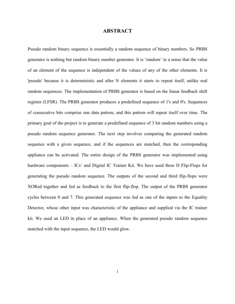
ABSTRACT Pseudo random binary sequence is essentially a random sequence of binary numbers. So PRBS generator is nothing but random binary number generator. It is ‘random’ in a sense that the value of an element of the sequence is independent of the values of any of the other elements. It is 'pseudo' because it is deterministic and after N elements it starts to repeat itself, unlike real random sequences. The implementation of PRBS generator is based on the linear feedback shift register (LFSR). The PRBS generator produces a predefined sequence of 1's and 0's. Sequences of consecutive bits comprise one data pattern, and this pattern will repeat itself over time. The primary goal of the project is to generate a predefined sequence of 3 bit random numbers using a pseudo random sequence generator. The next step involves comparing the generated random sequence with a given sequence, and if the sequences are matched, then the corresponding appliance can be activated. The entire design of the PRBS generator was implemented using hardware components – ICs’ and Digital IC Trainer Kit. We have used three D Flip-Flops for generating the pseudo random sequence. The outputs of the second and third flip-flops were XORed together and fed as feedback to the first flip-flop. The output of the PRBS generator cycles between 0 and 7. This generated sequence was fed as one of the inputs to the Equality Detector, whose other input was characteristic of the appliance and supplied via the IC trainer kit. We used an LED in place of an appliance. When the generated pseudo random sequence matched with the input sequence, the LED would glow. i TABLE OF CONTENTS CHAPTER NO 1 2 TITLE PAGE NO ABSTRACT i TABLE OF CONTENTS ii LIST OF FIGURES iv LIST OF TABLES v LIST OF ABBREVIATIONS vi ACTIVATION OF REMOTE DEVICES 1 1.1 Introduction 1 1.2 Device Activation 1 PSEUDO RANDOM SEQUENCE GENERATOR 2 2.1 Introduction 2 2.2 Linear Feedback Shift Register 3 2.2.1 Introduction 3 2.2.2 Feedback Action 5 2.2.3 Tapping Action 5 2.3 Properties of PRBS 3 6 GENERATION OF PSEUDO RANDOM 7 SEQUENCE 3.1 Introduction 7 3.2 IC 7474 7 3.2.1 Introduction 7 3.2.2 Pin Configuration 8 ii CHAPTER NO TITLE PAGE NO 3.3 IC 7486 4 9 3.3.1 Introduction 9 3.3.2 Pin Configuration 10 HARDWARE IMPLEMENTATION 11 4.1 Circuit Diagram of PRBS 11 4.2 Equality Detector(IC 74 HC688) 12 4.2.1 Introduction 12 4.2.2 Pin Configuration 13 4.3 Block Diagram for comparison 14 5 SNAPSHOT 15 6 CONCLUSION 16 REFERENCES 17 iii LIST OF FIGURES FIGURE NO TITLE PAGE NO 2.1 Illustration of Pseudo Random Number Cycle 2 2.2 A 3 Bit Shift Register 3 3.1 Pin Diagram of IC 7474 7 3.2 Pin Diagram of IC 7486 9 4.1 Circuit Diagram of PRBS 11 4.2 Pin Diagram of IC 74HC688 12 4.3 Block diagram for comparison 14 iv LIST OF TABLES TABLE NO TITLE PAGE NO 3.1 Pin Configuration of IC 7474 8 3.2 Truth Table for IC 7486 9 3.3 Pin configuration of IC 7486. 10 4.1 Pin Configuration of IC 74HC688 13 4.2 Truth Table for IC 74HC688 13 v LIST OF ABBREVIATIONS ABBREVIATION EXPANSION PRBS Pseudo Random Binary Sequence LFSR Linear Feedback Shift Register EX-OR Exclusive OR LED Light Emitting Diode vi

![Introduction [max 1 pg]](http://s3.studylib.net/store/data/007168054_1-d63441680c3a2b0b41ae7f89ed2aefb8-300x300.png)
![DSP-Based Testing – Fundamentals 50 PRBS (Pseudo Random Binary Sequence) [V93000]](http://s3.studylib.net/store/data/025472244_1-683a75db28c62cce4c01e6862699aeee-300x300.png)
