Section 6: Individual buildings not causing death
advertisement

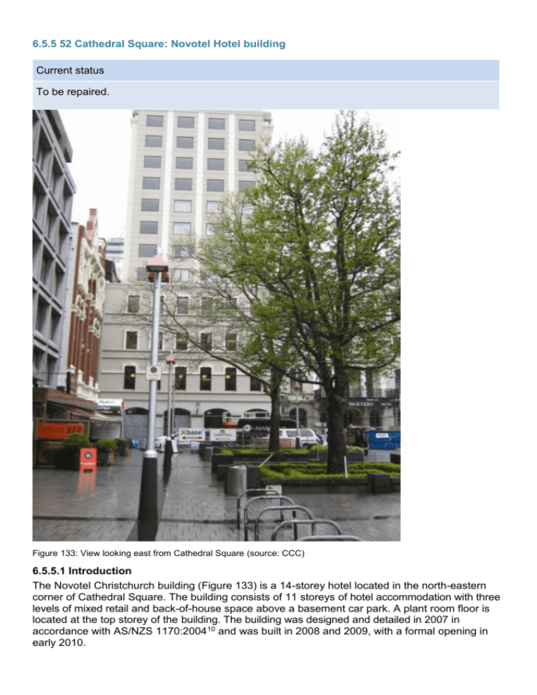
6.5.5 52 Cathedral Square: Novotel Hotel building Current status To be repaired. Figure 133: View looking east from Cathedral Square (source: CCC) 6.5.5.1 Introduction The Novotel Christchurch building (Figure 133) is a 14-storey hotel located in the north-eastern corner of Cathedral Square. The building consists of 11 storeys of hotel accommodation with three levels of mixed retail and back-of-house space above a basement car park. A plant room floor is located at the top storey of the building. The building was designed and detailed in 2007 in accordance with AS/NZS 1170:200410 and was built in 2008 and 2009, with a formal opening in early 2010. The Royal Commission has relied on the information provided by Lewis Bradford and Associates Ltd, Consulting Engineers, for the assessment of this building. The crack pattern observed in the southern shear wall above level 4 was of particular interest to us, as it illustrated the expected performance that was, unfortunately, not shown in many buildings. For this reason, the discussion is mainly limited to that part of the building, with some limited comment on the performance of the concrete panel cladding system. 6.5.5.2 Underlying ground conditions The Novotel site is underlain by sandy gravel, sand and silt to a depth of about 24m below the existing ground surface and overlying dense to very dense sandy gravels. There is a low to moderate risk of liquefaction in the soils underlying the site in a future ultimate limit state event. Under an ultimate limit state event the estimated liquefaction-induced total settlement was about 0–10mm. 6.5.5.3 Gravity load system The floors are built up from a metal tray (Traydec) with in situ concrete that varies in thickness from 125–170mm, depending on the location of the floor in the building. The floors are supported by steel beams, which in turn are supported on steel columns and the concrete walls. 6.5.5.4 Lateral load system Lateral forces are resisted by four reinforced concrete in situ walls with thicknesses that vary from 400mm at their base to 200mm at the top of the building. The location of the structural walls is shown on Figures 134 and 135 for the podium (to level 4) and the tower, respectively. Figure 134: Floor plan at level 1 (similar up to level 4). The major structural walls are shown in red Figure 135: Typical floor plan for the upper levels. The major structural walls are shown in red The details of the four walls are as follows: the wall on the eastern side of the building is 8m long above level 4 and below this level it occupies the full width of the building. The wall on the southern side of the building is 8m long above level 4 and below this level it is about 50 per cent longer. The wall on the northern side is more than 11m long and is continuous with an 8m wall on grid line D. These two walls act as an L-shaped structural member, with an appreciably higher lateral stiffness than the other two walls. With this arrangement the centre of stiffness is located about 5m from the northern wall and close to the intersection with grid line D. Owing to the change in length of two of the walls below level 4, the floors at levels 4 and 5 act as transfer diaphragms. Drag bars in all the floors were cast into the topping concrete to carry the inertial and transfer forces to the walls. 6.5.5.5 Performance of structural walls In the February earthquake the most intense shaking was in the east–west direction. As pointed out by Mr Lewis Bradford, because the centre of stiffness was in the northern half of the building, the greatest displacement imposed on the walls from this direction of earthquake actions would be in the southern wall. Inspection of the building showed that flexural cracking did occur above level 4 in this wall, with crack widths of 0.5–0.8mm. This zone was detailed as a potential plastic hinge region. The open cracks indicated that some plastic deformation developed in this zone. Of particular interest was a series of cracks developed at a spacing in the range of 150 to 500mm. Given the angle of the cracks and their reported widths, it was evident that they were due to flexure and axial loads. Because the cracks were inclined at less than 20 o to the horizontal it is unlikely that the horizontal reinforcement would have yielded. The wall at level 4 is 300mm thick and 8m long. Above this level it extends to a height of about 27.5m. The wall is reinforced with longitudinal bars at 200mm centres on each face. The 1m strips at each end of the 8m long wall each contain 10 32mm grade 300 bars (2 by 5). In between these two strips were sixty 20mm Grade 500 bars (2 by 30). The area of concrete surrounding each group of 10 32mm bars is 240,000mm2. Allowing for the transformed section, the stress the 32mm bars can induce in the concrete when they reach the yield point is 6.9Mpa, which should be more than adequate to ensure that secondary cracks can form. The corresponding tension stress that can be induced into the concrete surrounding the 20mm bars if they reach yield is 4.9MPa, clearly enough to cause the cracks initiated in the heavily reinforced end strips to extend into the mid- region of the wall. Creep and shrinkage in concrete can influence crack formation in structural walls. Assuming typical values for the concrete, namely, free shrinkage strain of the concrete of 500 x 10 -6, a creep factor of 2.5 and an axial stress due to gravity (based on gross section) of 1MPa, the resultant stresses in the concrete are of the order of 0.13MPa in tension and 46MPa in compression in the reinforcement. In this case, the creep due to gravity loads almost cancelled out the tensile stresses induced in the concrete by shrinkage. In the Lewis Bradford damage report, it was indicated that the cracks in the potential plastic hinge zone of the wall on the southern side of the building, just above level 4, were 0.5–0.8mm wide. On the basis of the cracks that can be observed in the diagram derived from a photograph provided by Lewis Bradford (see Figure 136), the material strain sustained by the potential plastic hinge can be assessed on the basis that the cracks were 0.8mm wide and the distance to the neutral axis from the extreme tension fibre was 7m. Based on these assumptions the material calculated, as detailed in NZS 3101:200612, was less than 15 per cent of the maximum permitted value given in that Standard. Figure 136: Crack patterns to the southern wall between levels 4 and 6 6.5.5.6 Performance of cladding panels Under the very high ground motions that occurred during the February earthquake, the building could have moved horizontally 50mm or more at each floor. This level of inter-storey movement would be expected to cause some damage to the cladding panels owing to tightening of normal construction tolerances. The damage observed was significantly exacerbated where panel movement was impeded by solid high strength mortar joints between panels, butt joints or steel brackets between panels. This is an example of where the construction of the building has not met the intention of the design, and the seismic gaps and joints have not been maintained as intended. This has also been discussed in section 6.3.4 of this Volume with the western wall of the building at 151 Worcester Street. Conclusions We conclude that: 1. The cladding panels were installed in some cases so that the seismic gaps were compromised. Some damage was expected given the magnitude of the February earthquake, but the damage was exacerbated by the installation deficiencies. 2. Cracking in the walls, particularly in the potential plastic hinge region in the southern wall immediately above level 4, has been well controlled by the quantity and arrangement of reinforcement in the wall. The performance of this wall was excellent given the seismic ground motion to which the building was subjected. The distribution of reinforcement in the walls ensured reinforcement strains remained in an acceptable range and cracking was well controlled. 6.6 Representative sample references 1. NZS 4203:1976. Code of practice for General Structural Design and Design Loadings for Buildings. Standards Association of New Zealand. 2. Elder, D. and McCahon, I. (1990). Near Surface Ground Hydrology and Excavation Dewatering in Christchurch”. Proceedings of Groundwater and Seepage Symposium, Auckland, New Zealand, May 1990. 3. Ministry of Works. (1968). Code of Practice, Design of Public Buildings, Office of Chief Structural Engineer. 4. NZSS 1900:1965. Chapter 8, Basic Design Loads. New Zealand Standards Institute. Available from Standards New Zealand. 5. NZSS 1900:1964. Chapter 9.3, Design and Construction, Concrete, New Zealand Standards Institute. Available from Standards New Zealand. 6. MacRae, G., Clifton, C. and Megget, L. (2011). Review of New Zealand Codes of Practice. Report submitted to the Royal Commission, August. Christchurch, New Zealand: Canterbury Earthquakes Royal Commission. 7. AS/NZS 1170.0:2002. Structural Design Actions – General principles. Standards New Zealand. 8. NZS 4219:1983. Specification for seismic resistance of engineering systems in buildings. Standards Association of New Zealand. Available from Standards New Zealand. 9. AS/NZS 60598.1:2003. Luminaires – Part 1: General requirements and tests. Standards New Zealand. 10. NZS 1170.5:2004. Structural Design Actions, Part 5: Earthquake actions – New Zealand. Standards New Zealand. 11. NZS 3101: Part 1: 1982. Code of practice for the design of concrete structures. Standards Association of New Zealand. Available from Standards New Zealand. 12. NZS 3101: Part 1:2006. Concrete Structures Standard, Part 1 – The Design of Concrete Structures. Standards New Zealand. 13. NZS 4203:1984. Loadings Code, Code of practice for General Structural Design and Design Loadings for Buildings. Standards Association of New Zealand. Available from Standards New Zealand. 14. Carr, A. J. (September 2011). Inelastic Response Spectra for the Christchurch Earthquake Records. Report to Canterbury Earthquakes Royal Commission. Christchurch, New Zealand: Canterbury Earthquakes Royal Commission. 15. Carr, Athol J. (2007). Ruaumoko User Manual, Volume 1-Theory. Department of Civil Engineering, University of Canterbury, New Zealand. Carr, Athol J. (2008). Ruaumoko User Manual, Volume 5-Appendices (Strength and Stiffness degradation models). Department of Civil Engineering, University of Canterbury, New Zealand. 16. GNS Science. (2012). Christchurch Deep Soil Accelerograms, Institute of Geological and Nuclear Sciences Limited. 17. Paulay, T. and Preistley M.J.N, Seismic design of reinforced concrete and masonry buildings. John Wiley and Sons Inc. 1992. 18. Restrepo-Posada, J. I. (1993). Seismic behaviour of connections between precast concrete elements. Research Report, 93-3, Dept. of Civil Engineering, University of Canterbury. 19. Fenwick, R., Bull, D. and Gardiner, D. (2010). Assessment of hollow-core floors for seismic performance. Research Report, 2010-02, Civil and Natural Resources Engineering, University of Canterbury. 20. Fenwick, R. C. and Megget, L. M. (1993). Elongation and load deformation characteristics of reinforced concrete members containing plastic hinges. Bulletin New Zealand Society for Earthquake Engineering Inc., 26(1). 21. Wuu, P. J. (1996). Deformations in plastic hinge zones of reinforced concrete beams in ductile frame structures subjected to inelastic cyclic loading. (ME thesis) Department of Civil Engineering, University of Auckland, Auckland, New Zealand. 22. NZS 4203:1992. Loadings Standard, Code of practice for General Structural Design and Design Loadings for Buildings. Standards New Zealand. 23. NZS 3101:Part 1:1995. Concrete Structures Standard, Part 1 – The Design of Concrete Structures. Standards New Zealand. 24. Euro-International Committee for Concrete (CEB). (1990). CEB-FIP Model Code 1990, Design Code. Thomas Telford, 1993. 25. Cubrinovski, M., and McCahon, I. (2011). Foundations on Deep Alluvial Soils. Report prepared for the Canterbury Earthquakes Royal Commission. Christchurch, New Zealand: Canterbury Earthquakes Royal Commission. 26. Fenwick, R. C., Bull, D. and Moss, P. (2011). Design of Floors Containing Precast Units in Multi-storey Buildings. Structural Engineering Society New Zealand (Inc.), Journal – April 2011. 27. Clifton, C., Bruneau, M., MacRae, G., Leon, R. and Fussell, A. (2011). Steel Building Damage from the Christchurch Earthquake Series of 2010 and 2011. Bulletin of the New Zealand Society for Earthquake Engineering Inc., 44(4). 28. NZS 3404 Parts 1 and 2:1997. Steel Structures Standard. Standards New Zealand.


