DMX16DOMan_HW - Simon
advertisement
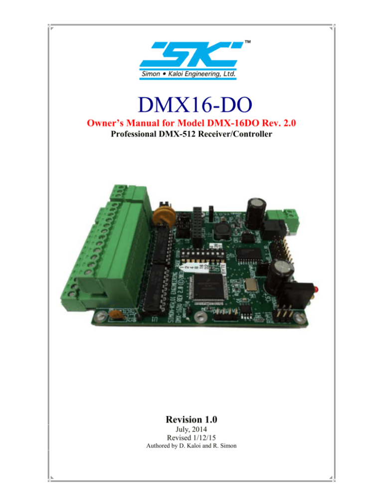
DMX16-DO Owner’s Manual for Model DMX-16DO Rev. 2.0 Professional DMX-512 Receiver/Controller Revision 1.0 July, 2014 Revised 1/12/15 Authored by D. Kaloi and R. Simon 2014 Simon-Kaloi Engineering, Ltd. Page 2 Table of Contents Important Safety Instructions _____________________________________________ 4 Introduction ___________________________________________________________ 5 System Block Diagram ___________________________________________________ 6 DMX-16DO Layout _____________________________________________________ 7 DMX Input/Output Connector ________________________________________________ 8 DMXTop Connector Jumper __________________________________________________ 8 Control Output Connector ____________________________________________________ 9 CHW,X Control Output Configuration Jumpers ________________________________ 10 CTLYZ Expansion Interface _________________________________________________ 10 DC Power Input ___________________________________________________________ 10 Servo Power Input _________________________________________________________ 10 SERVOPWR1 Servo Power Select Jumper _____________________________________ 10 Servo Interface ____________________________________________________________ 11 J2 Reset Switch ____________________________________________________________ 11 Status LEDs _______________________________________________________________ 11 Aux Serial I/F _____________________________________________________________ 11 DMX Address and Bit/Byte Switches __________________________________________ 11 Working with the DMX-16DO ___________________________________________ 13 Board Size and Mounting Holes ___________________________________________ 13 Features and Specifications _____________________________________________ 14 WARRANTY__________________________________________________________ 15 LIMITATION OF LIABILITY ___________________________________________ 15 Page 3 Important Safety Instructions Always follow basic safety precautions when using this product to reduce risk of injury from fire or electrical shock. Read and understand all instructions in the owner’s manual before using this product. Observe all warnings and instructions marked on the product. Disconnect this product from electrical power source before cleaning. Clean exposed parts with a damp soft cloth. Do not use cleaning agents or aerosols. Do not use this product near water or when wet. If this product gets wet, disconnect from power source immediately. Do not reconnect power until the unit has been dried thoroughly. This product should be mounted in a rack or placed on stable surface prior to use. Do not use this product if it has been dropped or damaged. Contact manufacturer for service or repair. Product should be mounted or placed in a location where cords and cables do not present a hazard. Use the provided mounting holes to mount being careful not to short any signal traces on the printed circuit board. NEVER DRILL OUT THE MOUNTING HOLES. THIS IS A MULTI-LAYER CIRCUIT BOARD AND DRILLING CAN CAUSE SHORTS AND OTHER PERMANENT DAMAGE. Cords and cables should be routed in a manner to prevent damage or abrasion. Use proper strain relief. Always make connections and disconnections with power off. Use power sources only as marked on the unit, specifically recommended in this manual or as supplied by the manufacturer. Do not overload electrical outlets or extension cords. This may increase risk of fire or electrical shock. Do not operate this product in rain, snow or other adverse conditions. If this unit does not operate properly, refer to the troubleshooting section of this manual. If the problem cannot be resolved contact the manufacturer for service or repair. No user serviceable parts are in this product. Removing the cover (for enclosed units) may cause exposure to dangerous voltages or other risks as well as void the warranty. Page 4 Introduction The DMX-16DO is a DMX-512 Receiver/Controller that accepts DMX-512 data and converts it to 16 bits of discrete output control and up to four servo control outputs. The discrete output controls are low-side open collector drivers with a typical sink current capability of 125mA each. Power for control is userprogrammable for 5V or DC input voltage (typically 12 or 24VDC). Provisions for optional and alternate high-side drivers are included. There is also an optional CHYZ_EXP1 board (shown below) that expands discrete output control by another 16 bits (32 bits total). The DMX-16DO is addressable and the base address can set via DIP-Switches. The DMX input can be looped through using the stacked three-pin connector. The DMX thru/output can also be buffered to serve as a repeater. Status lights are included as well as an alternate Servo Power Input for isolated or higher-power servo applications. WARNING: READ THIS MANUAL THOUROUGHLY BEFORE BEGINNING USE OF THE MINI-SAM II. ALL THE INFORMATION IN THIS MANUAL IS BELIEVED TO BE CORRECT HOWEVER IS SUBJECT TO CHANGE. WARNING: DO NOT DRILL OUT THE MOUNTING HOLES OR ANY OTHER PART OF THE DMX-16DO. THIS WILL DAMAGE THE MULTI-LAYER PCB AND VOID THE WARRANTY. Page 5 System Block Diagram Page 6 DMX-16DO Layout A top view of DMX-16DO Layout is shown below followed by the optional CHYZ Expansion Board. The user interfaces are identified and a detailed description of each follows on subsequent pages. (1) DMX Input/Output Connector (2) DMX XMIT Config Jumpers (4) CH WX Control Output Config Jumpers (5) CTLYZ Expansion I/F (6) DC Power Input Connector (7) Servo Power Connector (8) Servo Power Jumper (3) CTLWX1 Control Output Connector (9) Servo Interface (10) Reset Switch (11) Status LEDs (14) Control Driver ICs (U1, U2) (13) DMX Address/Mode Switches (12) Aux Serial I/F CHYZ EXPANSION BOARD (15) CH YZ Control Output Config Jumpers (16) CTLYZ Expansion I/F (17) GND Jumper Page 7 DMX Input/Output Connector (1) The top connector is used to output DMX data while the bottom connector is used to receive DMX data. Both inputs and outputs are differential. The signal polarity and ground are marked on the printed circuit board (PCB) and are the same for both the top and bottom pins. When looking at the rear of the PCB, for the top connector, Pin 1 (left most pin) is Tx+, Pin 2 is Tx-, and Pin 3 is Ground as per the table below. The balanced differential output impedance of the transmitter is typically 100 ohms. When connecting to DMX equipment, use a controlled impedance cable of 100 ohms (maximum of 120 ohms). You can daisy chain multiple units of DMX equipment (connecting in parallel) however, at the end of the chain a 1/2W 100 ohm (or 120 ohm for 120 ohm cable) should be placed across the “+” and “–” terminals of the last device. The section of this connector is the differential receiver. Pin 1 (left most) is Rx+, Pin 2 is Rx-, and Pin 3 is Ground per the table below. This receiver interface would usually be connected to a Mini-SAM, rPOD, or other DMX output as well as from another DMX-16DO’s DMX output connector. In the table below “T” refers to top connector and “B” to the bottom connector. DMX Pin 1T 2T 3T 1B 2B 3B Function Detail DMX TX+ DMX TXGROUND DMX RX + DMX RX GROUND RS-485 Output TX+ RS-485 Output TXSignal Ground RS-485 Input RX+ RS-485 Input RXSignal Ground DMXTop Connector Jumper (2) This jumper uses two shunts to select between the DMX Transmit (top connector) to the Bottom Rx Connector or to the on-board DMX Transmitter (Tx) as shown below: To loop to Rx To on-board Transmitter Connecting to the on-board transmitter can is useful in repeater applications. Page 8 Control Output Connector (3) There are 16 direct control outputs divided into two channels of eight, Channel W and Channel X. The standard driver is a low-side open collector ULN2803 that sinks current from the control power to the control ground. Typical sink current should be limited to less than 125mA per driver. There is an optional configuration for high-side driving. See the next section for more on this. The top “T” connector is the Control W (8 bits, power, and ground) and bottom “B” connector is the Control W (8 bits, power, and ground). The pin out is provided in the table that follows: J1 Pin 1T 2T 3T 4T 5T 6T 7T 8T 9T 10T 11T 12T 1B 2B 3B 4B 5B 6B 7B 8B 9B 10B 11B 12B Name Function CTLWGND CTLWPWR WOUT1 WOUT2 WOUT3 WOUT4 WOUT5 WOUT6 WOUT7 WOUT8 CTLWPWR CTLWGND CTLXGND CTLXPWR XOUT1 XOUT2 XOUT3 XOUT4 XOUT5 XOUT6 XOUT7 XOUT8 CTLXPWR CTLXGND CHW Control Gnd CHW Control Power CHW Control Output 1 CHW Control Output 2 CHW Control Output 3 CHW Control Output 4 CHW Control Output 5 CHW Control Output 6 CHW Control Output 7 CHW Control Output 8 CHW Control Power CHW Control Gnd CHX Control Gnd CHX Control Power CHX Control Output 1 CHX Control Output 2 CHX Control Output 3 CHX Control Output 4 CHX Control Output 5 CHX Control Output 6 CHX Control Output 7 CHX Control Output 8 CHX Control Power CHX Control Gnd IMPORTANT: FOR INDUCTIVE LOADS SUCH AS SOLENOIDS, ALWAYS MAKE SURE THE LOAD HAS FLYBACK DIODE MOUNTED AT OR IN THE LOAD TO PREVENT INDUCTIVE KICK DAMAGE TO THE LOAD AND MS-2E DRIVER CHIPS. NEVER SHORT ANY CONTOL OUTPUT DIRECTLY TO GROUND AS THIS WILL MOST LIKELY DAMAGE THE DRIVER. Page 9 CHW,X Control Output Configuration Jumpers (4) The equivalent schematic below shows how the control outputs connect to the output connector and how the control power can be selected as the input dc power (typically 24V), 5V regulated or user supplied power (CTLPWR1 jumper removed). Maximum external voltage should be limited to 30VDC. CTLYZ Expansion Interface (5) This interface is used to expand the number control outputs from 16 to 32 using the optional CHYZ Expansion Board. Make sure to align the pins of the CHYZ Expansion board so that every pin seats into the corresponding socket. DC Power Input (6) This is a two-pin euro-style connector. Connect a 10-24 Volt minimum 1 Amp regulated power supply to this connector. As you face the connector, the left terminal is designated as the positive power and the right terminal as the power return (gnd). The basic internal circuitry of DMX-16DO will draw typically under 100mA however, you must account for the power required for the loads of the control and servo outputs (depending on how many you used and how much current is required for each load). Servo Power Input (7) This is a two-pin spring-loaded connector that allows for a separate power supply for the servos (typically 5V regulated). This can be useful for heavy load servos that require high current. As you face the connector, the right terminal is designated as the positive power and the left terminal as the power return (gnd). SERVOPWR1 Servo Power Select Jumper (8) This jumper selects if the Servo Power is to be provided by the DMX-16DO’s internal 5V regulator (INT setting is the default) or the Servo Power Input Connector (EXT). Page 10 Servo Interface (9) Four servos are provided on this connector as shown in the diagram below. The first column of pins 1-3 (Column B) is Servo1, Col D is Servo2, Col F is Servo3 and Col G is Servo4. J2 Reset Switch (10) This switch resets the DMX-16DO. Cycling power also performs a reset. Status LEDs (11) These provide information on the status of the DMX-16DO. The top red LED illuminates when the unit is powered. The middle yellow LED illuminates when the unit is receiving valid DMX data. The bottom green LED illuminates when the unit is transmitting date from the on-board transmitter (not just looping thru Rx data). Aux Serial I/F (12) This interface provides, 5V power (pin 1), TTL level Rx (pin 2), TTL level Tx (pin 3), and ground (pin 4). DMX Address and Bit/Byte Switches (13) This first eight switches (marked 9 through 2 on the actual switch and LSB 1 to MSB 128) of this nine-position switch sets the base DMX address. The last switch (marked 1 on the actual switch) determines if the mode is bit or byte mode. The switches are considered on (logical one in binary terms) if the white switch tips are moved toward the “ON” position designated on the switch. The overall binary number N of the first eight switches is a binary number. Below are some examples of N and the mode based on switch positions. BYTE Mode: N = 0 BYTE Mode: N = 36 BIT Mode: N = 36 In the BYTE mode, a given DMX address represents eight different bits in the for the digital control output bits. Since each DMX address is represented in eight bits, this is the most efficient mode since it allows Page 11 that every in the DMX address to be controlled within one eight-bit word. For example, for a base address of one, each bit within the eight-bit word can be turned on and off from the controlling device (such as an MS-2E or rPOD-8.4) within that one word represented by CHW. The same would be true for all other DMX addresses up to address 512. In the byte mode, the base or starting DMX address for the DMX16DO is given by the formula: Byte Mode: First Channel (all eight bits addressable in one byte) Base Address = 2N + 1 where N = the address in binary provide by the switches, Nmax = 251 So if N = 0, the base address is 1 for the eight bits of CHW, CHX would have the automatic address of 2 and if the CHYZ Expansion board is used, CHY would be 3 and CHZ would be 4. If N were set to binary 1, the first address for CHW would be 3, followed by CHX at address 4, and so on. For the four servo channels, Servo1 would begin at an offset of five from the base address. Base Address = 2N + 5 where N = the address in binary provide by the switches, Nmax = 251 So if N = 0, the base address is 1 for the eight bits of CHW, CHX would have the automatic address of 2 and if the CHYZ Expansion board is used, CHY would be 3 and CHZ would be 4, and the Servo1 would have a DMX address of 5, Servo2 at address 6, Servo3 at address 7, and Servo4 at address 8. Bit Mode: First Channel (each bit is assigned to a DMX channel) Base Address = 2N + 1 where N = the address in binary provide by the switches, Nmax = 236 So if N = 0, the base address is 1 for the first bit of CHW, bit 8 would be address 8, CHX bit 1 would have the automatic address of 9 and if the CHYZ Expansion board is used, CHY bit 1 would be address 17 and CHZ bit 1 would be address 25, bit 8 of CHZ would be address 32. For the four servo channels, Servo1 would begin at an offset of 33 from the base address. Base Address = 2N + 33 where N = the address in binary provide by the switches, Nmax = 236 So if N = 0, the base address is 1 for the first bit of CHW, bit 8 would be address 8, CHX bit 1 would have the automatic address of 9 and if the CHYZ Expansion board is used, CHY bit 1 would be address 17 and CHZ bit 1 would be address 25, bit 8 of CHZ would be address 32, and the Servo1 would have a DMX address of 33, Servo2 at address 34, Servo3 at address 35, and Servo4 at address 36. Page 12 Working with the DMX-16DO Connect up the DMX-16DO output controls, servos, and DMX I/O before powering the unit. Use a DMX console, Simon-Kaloi Engineering Mini-SAM II, rPOD, or other device to program or run shows with the DMX-16DO. When using the Mini-SAM or rPOD, you will likely be using a DMX console, SKE Programmer Software, or the Sequence Programming Language to control the DMX-16DO. Board Size and Mounting Holes The PCB size and mounting holes are provided in the drawing below. Make sure that the board has enough clearance so that no electronic components will short to any conductive materials. Shorts to conductive surfaces will likely damage the board and void the warranty. WARNING: DO NOT DRILL OUT THE MOUNTING HOLES OR ANY OTHER PART OF THE DMX-16DO. THIS WILL DAMAGE THE MULTI-LAYER PCB AND VOID THE WARRANTY. Page 13 Features and Specifications DMX Addresses 1-512. 16 output controls expandable to 32. DMX In, Thru, and Out. Baud Rate 250Kbaud, one start bit, eight data bits, two stop bits, no parity. Input power 10-30VDC. Recommended Power Supply: 12-26 Volts DC @ 1-3 Amps (typical). Compact Enclosure; 5” L x 3” W x 1” H. Weight 3. 2 oz. Several possible mounting configurations. One year warranty. Specifications and appearance are subject to change without notice. Page 14 WARRANTY Simon-Kaloi Engineering, Ltd. ("SKE"), warrants this product to be free from defects for a period of one year from the date of purchase. If this product is defective under warranty, it must be returned to SKE or authorized service representative with proof of purchase (shipping costs for service are not covered by the warranty). This warranty is in lieu of all other warranties, expressed or implied, including, but not limited to, the implied warranties of merchantability or fitness for particular purpose, which are hereby expressly disclaimed. Warranty service must be performed by SKE or by SKE authorized service representative. Unauthorized service invalidates the warranty. LIMITATION OF LIABILITY SKE shall not be liable for any damage due to accident, abuse, misuse, normal wear and tear, or exceeding manufacturer’s specifications. The only remedy for breach of warranty is repair or replacement at the sole discretion of SKE. SKE shall not be liable for any incidental or consequential damages for breach of any expressed or implied warranty. SKE shall not be liable for any damage, whether arising in tort, contract or otherwise, for any amount in excess of the dealer cost of the product. Any claims for breach of warranty or contract must be brought within one year of acceptance of the product. Notice of such claims must be received by SKE within 60 days after acceptance of the product. All of the information in this document is believed to be accurate at the time of print however due to the dynamic nature of this product, all features, specifications, and other information are subject to change without notice. 31192 La Baya Drive Unit G • Westalke Village, CA 91362 Phone: (818) 707-8400 • Fax: (818) 707-8401 Website: email: sales@skeng.com Page 15
