Inspection Codes TG Meeting Agenda - Spring 2012
advertisement

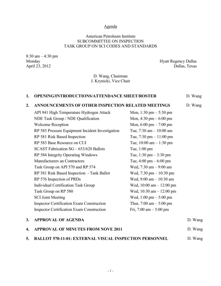
A Agenda American Petroleum Institute SUBCOMMITTEE ON INSPECTION TASK GROUP ON SCI CODES AND STANDARDS 8:30 am – 4:30 pm Monday April 23, 2012 Hyatt Regency Dallas Dallas, Texas D. Wang, Chairman J. Krynicki, Vice Chair 1. OPENING/INTRODUCTIONS/ATTENDANCE SHEET/ROSTER D. Wang 2. ANNOUNCEMENTS OF OTHER INSPECTION RELATED MEETINGS D. Wang API 941 High Temperature Hydrogen Attack NDE Task Group / NDE Qualification Welcome Reception RP 585 Pressure Equipment Incident Investigation RP 581 Risk Based Inspection RP 583 Base Resource on CUI SCAST Fabrication SG – 653/620 Ballots RP 584 Integrity Operating Windows Manufacturers an Contractors Task Group on API 570 and RP 574 RP 581 Risk Based Inspection - Tank Ballot RP 576 Inspection of PRDs Individual Certification Task Group Task Group on RP 580 SCI Joint Meeting Inspector Certification Exam Construction Inspector Certification Exam Construction Mon, 1:30 pm – 5:30 pm Mon, 4:30 pm – 6:00 pm Mon, 6:00 pm – 7:00 pm Tue, 7:30 am – 10:00 am Tue, 7:30 pm – 11:00 pm Tue, 10:00 am – 1:30 pm Tue, 1:00 pm Tue, 1:30 pm – 3:30 pm Tue, 4:00 pm – 6:00 pm Wed, 7:30 am – 9:00 am Wed, 7:30 pm – 10:30 pm Wed, 9:00 am – 10:30 am Wed, 10:00 am – 12:00 pm Wed, 10:30 am – 12:00 pm Wed, 1:00 pm – 5:00 pm Thur, 7:00 am – 5:00 pm Fri, 7:00 am – 5:00 pm 3. APPROVAL OF AGENDA D. Wang 4. APPROVAL OF MINUTES FROM NOVE 2011 D. Wang 5. BALLOT 570-11-01: EXTERNAL VISUAL INSPECTION PERSONNEL D. Wang -1- 6. BALLOT 570-2012-01: API 570 SECTION 8.3d, REQUEST TO MODIFY FOR CONSISTENCY WITH API 510 7. API 510 BALLOT RESOLUTION 8. OLD BUSINESS M. Geisenhoff A. 570 Draft Ballot: Alteration of Verbiage Around Inspection Intervals 9. J. Krynicki R. Sitton NEW BUSINESS A. 570 Draft Ballot: Addition of alternatives to PWHT to API 570 B. Technical Inquiry – 2012-510-01, Rerating Requirement for Inspector to Witness Attachment of Nameplate J. Monroe R. Konet 10. NEXT MEETING Los Angeles, California, November 12, 2012 11. ADJOURN -2- D. Wang -3- Ballot 570-2012-XX Title: Alteration of Verbiage Around Inspection Intervals Date: May 16, 2011 Contact: Name: Ryan Sitton Company: PinnacleAIS Phone: 281-598-1330 E-mail: ryan.sitton@pinnacleais.com Purpose: Improve verbiage to be more clear around requirements for UT intervals related to use of RBI. Source: Generated from Codes Task Group, Scorecard item 570-068 Revision: 0 Rationale: The current structure of section 6.3.2 and 6.3.3 around intervals for inspection is not completely clear. Notes: The following is the applicable sections from API 570, with tracked proposed changes. 6.3.2 Scheduling Inspections The owner/user or the inspector shall establish schedule for inspection activities such as thickness measurements and external visual inspections and, where applicable, for internal and supplemental inspections. The interval between inspections shall be based on a standard set of rules for inspection intervals or utilizing RBI. This interval shall be reviewed and adjusted as necessary after each inspection or significant change in operating conditions. General corrosion, localized corrosion, pitting, environmental cracking, and other applicable forms of deterioration mentioned in Section 5 shall be considered when establishing the various inspection intervals. 6.3.2.1 Rule Based Inspection Scheduling When the inspections are based on a set of rules, the interval between piping inspections shall be established and maintained using the following criteria: a) corrosion rate and remaining life calculations; b) piping service classification (see 6.3.4); c) applicable jurisdictional requirements; d) judgment of the inspector, the piping engineer, the piping engineer supervisor, or a materials specialist, based on operating conditions, previous inspection history, current inspection results, and conditions that may warrant supplemental inspections covered in 5.5.6. Thickness measurements should be scheduled at intervals that do not exceed the lesser of one half the remaining life determined from corrosion rates indicated in 7.1.1.1 or the maximum intervals recommended in Table 2. Shorter intervals may be appropriate under certain circumstances. Prior to using Table 2, corrosion rates shall be calculated in accordance with 7.1.1.1. Table 2 contains recommended maximum inspection intervals for Classes 1, 2 and 3 of piping services described in 6.3.4, as well as recommended intervals for injection points and S/A interfaces. Maximum -4- intervals for Class 4 piping are left to the determination of the owner/user depending upon reliability and business needs. 6.3.2.2 Inspection Scheduling Based on RBI An RBI assessment may be used to establish the appropriate timing of inspections, and increase or decrease the inspection limits described in Table 2. Similarly, the extent of inspection may be increased or decreased beyond the targets in Table 3, by an RBI assessment. When used to increase inspection interval limits or the extent of inspection, RBI assessments shall be conducted at intervals not to exceed the respective limits in Table 2, or more often if warranted by process, equipment, or consequence changes. These RBI assessments shall be reviewed and approved by a piping engineer and authorized piping inspector at intervals not to exceed the respective limits in Table 2, or more often if warranted by process, equipment, or consequence changes. -5- Ballot 570-2012-xx Title: Addition of alternatives to PWHT to API 570 Date: January 14, 2012 Contact: Name: Justin Monroe Company: Chevron Phone: (832)-790-9026 E-mail: justin.monroe@chevron.com Purpose: Currently API 570 does not allow for alternatives to PWHT. Both API 510 section 8.1.6.4.2 and API 653 section 11.3 provide similar alternatives of preheat and CDW. Source: Scorecard item 570-041 Revision: 0 Impact: This agenda item broadens the scope of API 570 by providing guidance on use of preheat and CDW as alteratives to PWHT, making API 570 more useful. Rationale: Since both API 510 and API 653 allow alternatives to PWHT, API 570 should be adjusted to align these documents. Proposal: The proposed change is shown below. 8.2.3.2 Preheating Preheat temperature used in making welding repairs shall be in accordance with the applicable code and qualified welding procedure. Exceptions for temporary repairs shall be approved by the piping engineer. Preheating to not less than 300 °F (150 °C) may be considered as an alternative to PWHT for alterations or repairs of piping systems initially PWHT as a code requirement (see note). This applies to piping constructed of the P-1 steels listed in ASME B31.3. P-3 steels, with the exception of Mn-Mo steels, also may receive the 300 °F (150 °C) minimum preheat alternative when the piping system operating temperature is high enough to provide reasonable toughness and when there is no identifiable hazard associated with pressure testing, shutdown, and startup. The inspector should determine that the minimum preheat temperature is measured and maintained. After welding, the joint should immediately be covered with insulation to slow the cooling rate. NOTE Preheating may not be considered as an alternative to environmental cracking prevention. Piping systems constructed of other steels initially requiring PWHT normally are postweld heat treated if alterations or repairs involving pressure retaining welding are performed. The use of the preheat alternative requires consultation with the piping engineer who should consider the potential for environmental cracking and whether the welding procedure will provide adequate toughness. Examples of situations where this alternative could be considered include seal welds, weld metal buildup of thin areas, and welding support clips. 8.2.4 Preheat or Controlled Deposition Welding Methods as Alternatives to Postweld Heat Treatment Preheat and controlled deposition welding, as described in 8.2.4.1 and 8.2.4.2, may be used in lieu of PWHT where PWHT is required by API 570 or was performed in the original construction but is inadvisable or mechanically unnecessary for the repair. Prior to using any alternative method, a metallurgical review conducted by an engineer shall be performed to assure the proposed alternative is suitable for the application. That review shall consider factors such as the reason for the original PWHT of the equipment, susceptibility to stress corrosion cracking, stresses in the location of the weld, susceptibility to high temperature hydrogen attack, susceptibility to creep, etc. -6- Selection of the welding method used shall be based on the rules of the construction code applicable to the work planned along with technical consideration of the adequacy of the weld in the as-welded condition at operating and pressure test conditions. When reference is made in this section to materials by the ASME designation, P-Number and Group Number, the requirements of this section apply to the applicable materials of the original code of construction, either ASME or other, which conform by chemical composition and mechanical properties to the ASME P-Number and Group Number designations. Process piping constructed of steels other than those listed in 8.2.4.1 and 8.2.4.2, that initially required PWHT, shall be postweld heat treated if alterations or repairs involving pressure boundary welding are performed. When one of the following methods is used as an alternative to PWHT, the PWHT joint efficiency factor may be continued if the factor has been used in the currently rated design. 8.2.4.1 Preheating Method (Notch Toughness Testing Not Required) The preheating method, when performed in lieu of PWHT, is limited to the following materials and weld processes: a. b. c. d. The materials shall be limited to P-No. 1, Group 1, 2, and 3, and to P-No. 3, Group 1 and 2 (excluding Mn-Mo steels in Group The welding shall be limited to the shielded-metal-arc welding (SMAW), gas-metal-arc welding (GMAW), and gas-tungstenarc, flux-cored arc welding (FCAW) and welding (GTAW) processes. The welders and welding procedures shall be qualified in accordance with the applicable rules of the original code of construction, except that the PWHT of the test coupon used to qualify the procedure shall be omitted. The weld area shall be preheated and maintained at a minimum temperature of 300°F (150°C) during welding. The 300°F (150°C) temperature should be checked to assure that 4 in. (100 mm) of the material or four times the material thickness (whichever is greater) on each side of the groove is maintained at the minimum temperature during welding. The maximum interpass temperature shall not exceed 600°F (315°C). When the weld does not penetrate through the full thickness of the material, the minimum preheat and maximum interpass temperatures need only be maintained at a distance of 4 in. (100 mm) or four times the depth of the repair weld, whichever is greater on each side of the joint. Note: Notch toughness testing is not required when using this preheat method in lieu of PWHT. 8.2.4.2 Controlled-deposition Welding Method (Notch Toughness Testing Required) The controlled-deposition welding method may be used in lieu of PWHT in accordance with the following: a. Notch toughness testing, such as that established by ASME B31.1, Chapter III Section 323, is necessary when impact tests are required by the original code of construction or the construction code applicable to the work planned. b. The materials shall be limited to P-No. 1, P-No. 3, and P-No. 4 steels. c. The welding shall be limited to the shielded-metal-arc welding (SMAW), gas-metal-arc welding (GMAW), flux-cored arc welding (FCAW), and gas-tungstenarc welding (GTAW) processes. d. A weld procedure specification shall be developed and qualified for each application. The welding procedure shall define the preheat temperature and interpass temperature and include the post heating temperature requirement in f(8). The qualification thickness for the test plates and repair grooves shall be in accordance with Table 8-1. The test material for the welding procedure qualification shall be of the same material specification (including specification type, grade, class and condition of heat treatment) as the original material specification for the repair. If the original material specification is obsolete, the test material used should conform as much as possible to the material used for construction, but in no case shall the material be lower in strength or have a carbon content of more than 0.35%. e. When impact tests are required by the construction code applicable to the work planned, the PQR shall include sufficient tests to determine if the toughness of the weld metal and the heat-affected zone of the base metal in the as-welded condition is adequate at the minimum design metal temperature (such as the criteria used in ASME Code Section VIII: Division I, parts UG-84 and UCS 66). If special hardness limits are necessary (for -7- f. example, as set forth in NACE RP 0472 and MR 0103) for corrosion resistance, the PQR shall include hardness tests as well. The WPS shall include the following additional requirements: 1. The supplementary essential variables of ASME Code, Section IX, Paragraph QW-250, shall apply. 2. The maximum weld heat input for each layer shall not exceed that used in the procedure qualification test. 3. The minimum preheat temperature for welding shall not be less than that used in the procedure qualification test. 4. The maximum interpass temperature for welding shall not be greater than that used in the procedure qualification test. 5. The preheat temperature shall be checked to assure that 4 in. (100 mm) of the material or four times the material thickness (whichever is greater) on each side of the weld joint will be maintained at the minimum temperature during welding. When the weld does not penetrate through the full thickness of the material, the minimum preheat temperature need only be maintained at a distance of 4 in. (100 mm) or four times the depth of the repair weld, whichever is greater on each side of the joint. 6. For the welding processes in 8.1.6.4.2.3c, use only electrodes and filler metals that are classified by the filler metal specification with an optional supplemental diffusible-hydrogen designator of H8 or lower. When shielding gases are used with a process, the gas shall exhibit a dew point that is no higher than –60°F (–50°C). Surfaces on which welding will be done shall be maintained in a dry condition during welding and free of rust, mill scale and hydrogen producing contaminants such as oil, grease and other organic materials. 7. The welding technique shall be a controlled-deposition, temper-bead or half-bead technique. The specific technique shall be used in the procedure qualification test. 8. For welds made by SMAW, after completion of welding and without allowing the weldment to cool below the minimum preheat temperature, the temperature of the weldment shall be raised to a temperature of 500°F ± 50°F (260°C ± 30°C) for a minimum period of two hours to assist out-gassing diffusion of any weld metal hydrogen picked up during welding. This hydrogen bake-out treatment may be omitted provided the electrode used is classified by the filler metal specification with an optional supplemental diffusible-hydrogen designator of H4 (such as E7018-H4). 9. After the finished repair weld has cooled to ambient temperature, the final temper bead reinforcement layer shall be removed substantially flush with the surface of the base material. Refer to WRC Bulletin 412 for additional supporting technical information regarding controlled deposition welding. Table 8-1—Welding Methods as Alternatives to Postweld Heat Treatment Qualification Thickness for Test Plates and Repair Grooves Depth t of Test Groove Repair Groove Depth Thickness T of Test Coupon Thickness Base Metal Welded Qualified Welded Qualified t <t < 2 in (50 mm) <T t <t ≥ 2 in (50 mm) 2 in (50 mm) to unlimited a The depth of the groove used for procedure qualification must be deep enough to allow removal of the required test specimen -8- Technical Inquiry – 2012-510-01 Publication Type: Code Publication Number: 510 Edition: Ninth Edition, June 2006 Addendum/Errata: Number: Section Referenced: 8.2.2 Subject: Rerating requirement for inspector to witnesses attachment of nameplate or additional stamping As an Inspector in Refining for ConocoPhillips for over 20 years, it was seldom a problem to physically witness or attach the rerate tags myself. I am in a different world now in Upstream for ConocoPhillips and for me to physically be present for each attachment may require long drives, even airline flights or hiring contract API 510 Inspectors to "fill in" for me when it is impractical for me to be there. Background: My inquiry deals with the intent of "witness". Would it be considered meeting the intent of the code if someone else attached the nameplate that was not a Certified API 510 Inspector and sent photos confirming its placement and RV set pressure for Inspector approval at a remote location? Older versions of the Code used to say that the Inspector had to "oversee" the attachment and even that appears to me to be subject to interpretation for if the intent is that the Inspector be physically present. Below is the section for consideration copied from API 510 9th edition, June 2006: 8.2 Rerating 8.2.2 The pressure vessel rerating will be considered complete when the inspector witnesses the attachment of an additional nameplate or additional stamping that carries the information in Figure 8-1. Question: Is the intent of the Code in 8.2.2 to require the physical presence on site of the Inspector in order to "witness" the attachment of the additional nameplate or stamping? First Name: Kelley -9- Last Name: VanLoon Email: Kelley.L.VanLoon@ConocoPhillips.com Company: ConocoPhillips Phone: 806-275-3486 Proposed Response: Yes - 10 -


