Dynamic_simulation_of_electron
advertisement
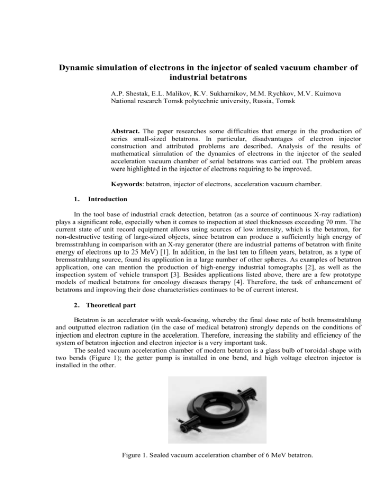
Dynamic simulation of electrons in the injector of sealed vacuum chamber of industrial betatrons A.P. Shestak, E.L. Malikov, K.V. Sukharnikov, M.M. Rychkov, M.V. Kuimova National research Tomsk polytechnic university, Russia, Tomsk Abstract. The paper researches some difficulties that emerge in the production of series small-sized betatrons. In particular, disadvantages of electron injector construction and attributed problems are described. Analysis of the results of mathematical simulation of the dynamics of electrons in the injector of the sealed acceleration vacuum chamber of serial betatrons was carried out. The problem areas were highlighted in the injector of electrons requiring to be improved. Keywords: betatron, injector of electrons, acceleration vacuum chamber. 1. Introduction In the tool base of industrial crack detection, betatron (as a source of continuous X-ray radiation) plays a significant role, especially when it comes to inspection at steel thicknesses exceeding 70 mm. The current state of unit record equipment allows using sources of low intensity, which is the betatron, for non-destructive testing of large-sized objects, since betatron can produce a sufficiently high energy of bremsstrahlung in comparison with an X-ray generator (there are industrial patterns of betatron with finite energy of electrons up to 25 MeV) [1]. In addition, in the last ten to fifteen years, betatron, as a type of bremsstrahlung source, found its application in a large number of other spheres. As examples of betatron application, one can mention the production of high-energy industrial tomographs [2], as well as the inspection system of vehicle transport [3]. Besides applications listed above, there are a few prototype models of medical betatrons for oncology diseases therapy [4]. Therefore, the task of enhancement of betatrons and improving their dose characteristics continues to be of current interest. 2. Theoretical part Betatron is an accelerator with weak-focusing, whereby the final dose rate of both bremsstrahlung and outputted electron radiation (in the case of medical betatron) strongly depends on the conditions of injection and electron capture in the acceleration. Therefore, increasing the stability and efficiency of the system of betatron injection and electron injector is a very important task. The sealed vacuum acceleration chamber of modern betatron is a glass bulb of toroidal-shape with two bends (Figure 1); the getter pump is installed in one bend, and high voltage electron injector is installed in the other. Figure 1. Sealed vacuum acceleration chamber of 6 MeV betatron. The acceleration vacuum chamber is installed into the working pole gap of a betatron so that the output slit of electron injector is within the radius of injection, i.e. in the position of maximum electron capture in acceleration. The capture efficiency is mainly determined by the electron optics of the injector. This dependence imposes strict requirements on the dimensional tolerances in the manufacture of injection unit of the betatron acceleration chamber. The production of the injector unit is relevant to “adaptor” assembly; i.e., the main splits between the anode and the focusing electrode are given by special technological mountings. However, the existing construction has a parameter whose value is visually monitored. It is referred to the depth of the cathode installation in the focusing electrode (parameter «ɑ» Figure 2). Also, there is another problem associated with the cathode. Injector cathode of electron betatron relates to a filamentary type and because of design features is subjected to thermal expansion, which results in distortion of electron optics of the injector as a whole. Figure 2. General form and cut of electron injector of betatron. 3. Simulation Mathematical simulation was carried out with the finite-difference method of the dependence of the coefficient of injector’s current transmission on the depth of the cathode installation into the focusing electrode for the impact assessment of this parameter on the optics of the injector. In this case the current transmission coefficient is the ratio of the total charge of the electrons emerging from the injector to the total charge of the electrons that overcome the accelerating gap of the injector, some of which face the anode. Basic design elements that determine the electron optics were used in the geometric model of the injector. To simplify calculations the spiral cathode was replaced with the cylindrical of the same dimensions. Another simplification relates to the absence of the magnetic field. On the one hand, such simplification is justified by the fact that during the injection, the value of the magnetic field induction corresponds to the radius of electron injection, which is, for example, 78 mm for a betatron of 7 MeV, while the accelerating split in the injector is 3.4 mm. Thus, the electron beam, accounting for the magnetic field, will deviate from the axis of the focusing inside the injector at a distance equal to 0.074 mm (the size of the anode slit trench is 1.5 mm). On the other hand, the magnetic field is not provided on the specially designed vacuum stand to check the results of modeling (including and due to the abovedescribed reason). The following electrical parameters were based on the mathematical model: injection current is 1 A; accelerating difference of electric potential is 40 kV. It is worth mentioning that in the model as well as in a virtual injector, the anode and the focusing electrode are at the same electric potential. This fact negatively affects the focusing properties of the injector and as practice shows [5] considerably reduces the variation limits of deviation of the cathode’s size landing inside the focusing electrode. As a result of simulation we obtained the dependence of the coefficient of the current transmission Ki of injector on ɑ is installation depth of the cathode into the focusing electrode. The reading of distance ɑ was conducted from the exit plane of the focusing electrode to the parallel plane of the nearest surface of the cylindrical cathode (Figure 2). In simulation, the value of the parameter ɑ varied in the range from 0 to 2 mm and at a pitch of 0.1 mm. The result of simulation is graphically presented in Figure 3. Figure 3. Graphical view of dependence Ki(a) It is clearly seen that the maximum of the coefficient of current transmission is 0.92 and occurs at the installation depth of cathode of 1.1 mm, implying that about 8% of the electrons are lost on the anode. It is important to emphasize that the current between the focusing electrode and anode Ife is not equal to the emission current from the cathode, as a portion of the electrons emitted from the cathode may undergo collision both with the cathode and the focusing electrode. Also, the number of these electrons increases with increased depth of cathode installation (Figure 4), and the current value Ife decreases. Figure 4. Graphical view of dependence Ife(ɑ) As a result of the described processes, the current of the injector Iinj has the dependence Iinj(ɑ). Figure 5 shows that the maximum current of the injector occurs at the depth of cathode installation, 1.1 mm. Figure 5. Graphical view of dependence Iinj(ɑ) The low level of injection current at cathode installation depths less than 1.1 mm is explained by the steradian predominance of collisional process of electrons with the anode. Figure 6 shows the distribution of the current density of the injector in the horizontal plane of the interpole space of a betatron, where ɑ = 0. And fall of current density for ɑ more than 1.1 mm is due to the increasing number of collisions of electrons with the cathode and the focusing electrode (Figure 7). Figure 6. Distribution of current density of the injector at ɑ = 0 Figure 7. Distribution of current density of the injector at ɑ = 1.2 mm 4. Conclusion As the result of mathematical simulation, we obtained the dependence of the coefficient of the current transmission of the injector on the depth of the cathode installation into the focusing electrode. This dependence of the coefficient is compatible with experimental data in [5]. In addition, the graphical view of this relationship (Figure 3) allows setting the acceptable limits of the installation of the cathode into the focusing electrode. With Ki(ɑ) and Iinj(ɑ) for the independent parameter ɑ, one can set the following value with deviation limits from: ɑ = 1, 1+0,2 −0,1 mm. Within the range of values of parameter ɑ, the coefficient of current transmission varies by no more than 6% from optimum. If parameter ɑ deviates above specified limits, the value of the coefficient of current transmission falls below 85%. We should not forget about another problem of currently available electron injectors. Deformation of the filamentary cathode due to thermal expansion can introduce significant distortions in the optics of the injector. The method by which the cathode of the injector for the betatron is produced, includes the process of carbonization of the cathode blank from thoriated tungsten wire. Thus the degree of carbonization should not be less than the value specified in the technical specifications (i.e., it may differ from the values of certain specifications upward). As a result of this manufacturing process, the structural stiffness of the cathode varies, and the corresponding deformation due to thermal expansion of a single cathode is not predictable. Described in this article are drawbacks of currently available betatron injector technology, which lead directly or indirectly to highly-substantial variation of dose rate of bremsstrahlung, which is the main parameter of acceleration chambers. For example, according to experimental data, dispersion of dose rate for chambers BUK-6 ranged from 2 to 10 R/min, in the lot of 90 pieces (data was taken from the report for internal use of INT “TPU” in 2008). Summarizing all above mentioned, it is necessary to change the design/construction of the injection unit of the acceleration chamber of betatron to obtain the required repeatability the dose rate of bremsstrahlung in a narrower range which is the main characteristics of the chambers. At the moment, this is achieved by screening of acceleration cameras at the stage of their installation in the betatron. In particular cases, the percentage of rejections reaches the value of 50% (at an average, rejections is 25%). Among possible solutions to the problem of repeatability of the output characteristics of betatron chambers, one can offer the transition to new construction materials, such as ceramics (now the injector is mounted on a glass pedestal), and the change in the actual design of the injector. References [1] JME - ADVANCED INSPECTION SYSTEMS [electronic resource]/BETATRON PORTABLE X-RAY Access: http://www.jme.co.uk/JME-Products-Betatron.aspx (Accessed February 05 2015) [2] E. I. Vaynberg, V. A. Kasyanov, V. L. Chakhlov, M. M. Stein EXPERIENCE OF USING SMALL-SIZE BETATRON MIB-5 IN THE STRUCTURE OF INDUSTRIAL COMPUTED TOMOGRAPH BT-500XA http://www.ndt.net/article/wcndt2004/pdf/radiography/102_stein.pdf (Accessed February 05 2015) [3] Bjorkholm P., Johnson J. Cargo Examination using the X-ray Radiation of High Energy. – Cargo Security Intelligence. October 2004, Pages 141-147. [4] David J. Lochman. Therapy in cancer of the head and neck with the betatron electron beam / The American Journal of Surgery, Volume 98, Issue 6, December 1959, Pages 847-850 [5] G. Baciu The electron injection process in the betatron .//Nuclear Instruments and Methods, Volume 26, February–March 1964, Pages 173-178
