3493-10068-1
advertisement

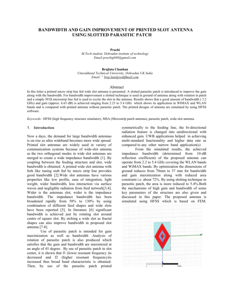
BANDWIDTH AND GAIN IMPROVEMENT OF PRINTED SLOT ANTENNA USING SLOTTED PARASITIC PATCH Prachi M.Tech student, Dehradun institute of technology Email:prachig048@gmail.com Brajlata Chauhan Uttarakhand Technical University, Dehradun UK India Email: 1. braj.lata@rediffmail.com Abstract In this letter a printed micro strip line fed wide slot antenna is presented. A slotted parasitic patch is introduced to improve the gain along with the bandwidth. For bandwidth improvement a slotted technique is used in ground of antenna along with rotation in patch and a simple 50 Ώ microstrip line fed is used to excite the slot in the antenna. Results shows that a good amount of bandwidth ( 3.2 GHz) and gain (approx. 6.63 dB) is achieved ranging from 2.23 to 5.4 GHz which shows its application in WIMAX and WLAN bands and is compared with printed antenna without parasitic patch. The printed designs of antenna are simulated by using HFSS software. Keywords– HFSS (high frequency structure simulator), MSA (Microstrip patch antenna), parasitic patch, wide-slot antenna. 1. Introduction Now a days, the demand for large bandwidth antennas is on rise as ultra wideband becomes more wide spread. Printed slot antennas are widely used in variety of communication systems because of wide-slot antenna as the two orthogonal modes in wide slot antennas are merged to create a wide impedance bandwidth [1]. By coupling between the feeding structure and slot, wide bandwidth is obtained. A printed wide slot antenna with fork like tuning stub fed by micro strip line provides good bandwidth [2].Wide slot antennas have various properties like low profile, ease of integration, light weight, wider bandwidth, less interaction via surface waves and negligible radiation from feed network[3,4]. Wider is the antennas slot, wider is the impedance bandwidth. The impedance bandwidth has been broadened rapidly from 58% to 130% by using combination of different feed shapes and wide slots have been reported [5]. In literature [6] significant bandwidth is achieved just by rotating slot around centre of square slot. By etching a wide slot as fractal shapes can also improve bandwidth in proposed slot antenna [7-8]. Use of parasitic patch is intended for gain maximization as well as bandwidth .Analysis of rotation of parasitic patch is also produced which satisfies that the gain and bandwidth are maximized at an angle of 45 degree. By use of parasitic patch in slot center, it is shown that f1 (lower resonant frequency )is decreased and f2 (higher resonant frequency)is increased thus broad band characteristic is obtained. Then, by use of the parasitic patch printed symmetrically to the feeding line, the bi-directional radiation feature is changed into unidirectional with enhanced gain. UWB applications helped in achieving multi-standard functionality and higher data rate as compared to any other narrow band application(s) From the simulated results, the achieved impedance bandwidth (determined from 10-dB reflection coefficient) of the proposed antenna can operate from 2.2 to 5.4 GHz covering the WLAN bands and WiMAX bands. By optimization the dimensions of ground reduces from 70mm to 37 mm for bandwidth and gain maximization along with reduced area constraint i.e. about 72%. By using slotting technique in parasitic patch, the area is more reduced to 5.4%.Both the mechanisms of high gain and bandwidth of some key parameters of the structure are also given and discussed in this paper. The proposed antenna is simulated using HFSS which is based on FEM. Figure 1 front view of slot antenna with slotted parasitic patch Return loss is measure of how well antenna matching is done. The return loss of proposed antenna is approx. -21 and -18dB at resonant frequencies 2.4 and 4.9GHz as shown in figure 3. II. ANTENNA GEOMETRY AND DESIGN Name X XY Plot 10 Y HFSSDesign1 m10.00 2.2521 -9.9821 m2 dB(S(1,1)) Setup1 : Sweep m3-2.50 4.9570 -19.8204 m4 ANSOFT Curve Info 5.4499 -10.0815 2.4355 -20.2484 -5.00 -7.50 m1 m2 dB(S(1,1)) Proposed design of micro strip parasitic patch antenna is shown in the figure.1. A concept obtained from the Yagi-Uda antenna by using parasitic patches to enhance antenna gains was investigated. The proposed antenna has a simple geometry, consist of square slot and parasitic patch with some angle of rotation .A slot is created in parasitic patch having dimensions 5x5mm.The printed square slot antenna’s dimensions are 24.7x24.7 mm2 which is printed on FR-4 substrate having thickness 1.6mm and relative permittivity 4.4. The ground dimensions are taken as 37x37 mm2. The square slot is fed by 50ohm micro strip line which is printed on substrate. The feed line shown in figure is having the dimensions of 3x31.5mm. In this paper, the shape of slot is taken to be square and slots in the ground plane and parasitic patch are rotated at an angle 45°. -10.00 -12.50 -15.00 -17.50 m3 m4 -20.00 -22.50 2.00 2.50 3.00 3.50 4.00 Freq [GHz] 4.50 5.00 5.50 6.00 Figure 3 Return loss Name X XY Plot 16 Y HFSSDesign2 m10.00 2.2521 -10.0449 m2 dB(S(1,1)) Setup1 : Sweep l='5mm' m3-2.50 4.9456 -19.8433 m4 ANSOFT Curve Info 5.4613 -9.8109 2.4355 -21.0383 -5.00 dB(S(1,1)) Setup1 : Sweep l='6mm' -7.50 dB(S(1,1)) Setup1 : Sweep l='6.5mm' m2 dB(S(1,1)) m1 -10.00 dB(S(1,1)) Setup1 : Sweep l='7mm' -12.50 -15.00 -17.50 m3 -20.00 Figure 2 back view of slot antenna showing feed line m4 -22.50 2.00 For bandwidth maximization the square slot rotation is performed at an angle of 45 degree and parasitic patch is applied having the dimensions of 12x12mm2 and for gain maximization the slotted parasitic patch is also rotated at angle of 45 degree. Thus angle of rotation of parasitic patch provides us gain improvement. II. RESULT ANALYSIS A parametric study is carried out to study the effect of size of slot in parasitic patch on various parameters such as return loss, bandwidth and gain. The size of slot is varied from 5 to 7mm and is shown in figure 4. A. Return loss of proposed antenna 2.50 3.00 3.50 4.00 Freq [GHz] 4.50 5.00 5.50 6.00 Figure 4 simulated reflection coefficient vs freq From the simulated result and parametric study, it is shown that bandwidth has negligible effect on size of slot but shows some effect on return loss and gain on introducing a slot in parasitic patch, the gain is improved and is shown in the table. Size of slot(mm) 5 6 Fr(GHz) Return loss 2.4&4.9 -21,-18 2.4&4.9 -20,-18 Bandwidth (GHz) 3.2 3.2 Gain (dB) 6.71 5.13 7 2.4&4.9 -20,-19 3.2 6.63 Table 1 B. Bandwidth of proposed antenna : Bandwidth describes the range of frequencies over which the antenna can properly radiate or receive energy. We can see that on changing the values of ground plane have effect on the bandwidth of proposed antenna. Substrate thickness is another important parameter in achieving wide band performance. The impedance bandwidth obtained from the simulation results ranging from 2.25 to 5.46 GHz at 10dB return loss. That is 3.21 GHz bandwidth is achieved as shown in above figure. bandwidth so obtained is about 2GHz (5.4-3.4GHz) .The gain so obtained in this case is about 5.4dB as shown below. The design of reference antenna without parasitic patch is shown in figure 6. C. Gain of proposed antenna : Gain is defined as the ability of antenna to concentrate energy in a narrow angular region( a directive beam). Figure 6 without parasitic patch Name X XY Plot 5 Y HFSSDesign1 m10.00 3.4269 -10.1979 m2 5.4469 -10.0224 m3 3.8277 -39.9066 -5.00 ANSOFT Curve Info dB(S(1,1)) Setup1 : Sweep m2 m1 -10.00 dB(S(1,1)) -15.00 -20.00 -25.00 Figure 5 gain The results on the basis of rotation of parasitic patch are shown in the given table. The gain so obtained at angle 45degree is maximum i.e. 6.71dB and is verified by the given table. II. COMPARISON ANALYSIS The comparison has been made between without parasitic patch and with slotted parasitic patch on the basis of return loss, bandwidth and gain. The reference antenna i.e. without parasitic patch has ground dimensions of 70x70mm2 and with parasitic patch has dimensions of 37x37mm2 thus area is reduced up to 72%.The return loss of reference antenna is -39 dB at resonant frequency of 3.8GHz which is shown in fig 7 which shows very good impedance matching. The -30.00 -35.00 m3 -40.00 2.00 2.50 3.00 3.50 4.00 Freq [GHz] 4.50 5.00 5.50 6.00 Figure 7 return loss of reference antenna The proposed antenna i.e. with parasitic patch has ground dimensions of 37x37mm2.The variations are in the dimensions of ground and all other parameters are same as given in design methodology. The return loss of proposed antenna is about -20dB and the bandwidth so obtained is about 3.2 GHz which is far better than reference antenna .The results of gain is about 6.71dB which is also better than reference antenna only by rotated slot in parasitic patch. 8. Figure 8 gain of reference antenna II. CONCLUSION A printed slot antenna with parasitic patches has been implemented and studied in this letter. The bandwidth of proposed slot antennas by introducing a parasitic patch into rotated square slot can significantly increased up to 3.2 GHz. On rotating the parasitic patch at angle 45 and also slot on the parasitic patch which is also rotated at same angle, then gain is enhanced up to 6.71 dB thus improving the performance of antenna. The proposed antenna is applicable for WIMAX and WLAN bands. References: 1. 2. 3. 4. 5. 6. 7. M. Kahrizi, T. K. Sarkar and Z. A. Maricevic, “Analysis of a wide radiating slot in the groundplane of a microstrip line,”IEEE Trans. Antennas Propag., vol. 41, no. 1, pp. 29–37, Jan. 1993.. J. Y. Sze and K. L. Wong, “Bandwidth enhancement of a microstrip line-fed printed wide-slot antenna,” IEEE Trans. Antennas Propag., vol. 49, no. 7, pp. 1020–1024, Jul. 2001. W.L Stutz man and G.A Thiele. “Antenna Theory and Design”. John Wiley&Sons, Inc, 1998. Girish Kumar and K.P Ray,” Broadband Microstrip Antennas”, Artech House, 2003, pp 3-5. S.-W. Qu, C. Ruan, and B.-Z. Wang, “Bandwidth enhancement of wide slot antenna fed by CPW and microstrip line,”IEEE Antennas Wireless Propag. Lett. vol. 5, pp. 15–17, 2006. J.-Y. Jan and J.-W. Su, “Bandwidth enhancement of a printed wide-slot antenna with a rotated slot,”IEEE Trans. Antennas Propag. vol. 53,no. 6, pp. 2111–2114, Jun. 2005. W.-L.Chen,G.-M.Wang,andC.X. Zhang, “Bandwidth enhancement of a microstrip-line-fed printed wide-slot antenna with a fractal-shaped slot,”IEEE Trans. Antennas Propag., vol. 57, no. 7, pp. 2176–2179,Jul. 2009. D. D. Krishna, M. Gopikrihna, C. K. Aanandan, P. Mohanan, and K.Vasudevan, “Compact wideband Koch fractal printed slot antenna,”Microw. Antennas Propag., vol. 3, no. 5, pp. 782–789, Aug. 2009


